IMPORTANT
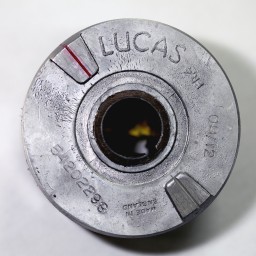 Most Lucas alternator rotors have timing marks, lines on the rotor, in two locations. These are a hold over from the ill fated Triumph Fury and BSA Bantam and its 180° crankshaft.
To set up your Boyer you will be using the full advance timing mark that aligns with the timing pointer when the piston is near Top Dead Center.
Remove the spark plugs and with the motorcycle on its center stand and in high gear, rotate the rear wheel until the piston or pistons are at Top Dead Center.
Then rotate the rear wheel backward a bit until the timing pointer aligns with the timing mark on the rotor. This will place the piston at Full Advance Before Top Dead Center. To make things easier in the future put a little nail polish in the groove that makes the line.
Now go to the other side of the motorcycle and align the small timing rotor screw head with the appropriate hole in the plastic plate. There is a hole for clockwise rotation (Triumph) and another for counter clockwise (BSA and Norton).
Mark this timing mark so you can easily identify it in the future.
If you are having problems getting a spark, even though the box is wired properly, check to see if the engine is grounded to the battery. The ignition box, coils and engine must share a common ground with the battery (or capacitor or Power Box if not using a battery). Do not assume that the engine is grounded by the mounting bolts!!
Start Diagnosing Problems with the Timing Plate
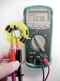 Connect ohmmeter leads to Black/Yellow and Black/White wires as shown.
Turn the ohmmeter on and read resistance.
For a twin Triumph or Norton timing plate, typical resistance is 137 ohms. For a triple, typical resistance would be 48 ohms. These readings will varying depending upon the condition of the meter’s battery and the resistance of the meter’s leads. If the meter doesn’t “zero” when you put the leads together take that into consideration when you measure the coils resistance.
The resistance of individual coils should be approximately the same. If one coil measures 66 ohms the other should also measure 66 ohms.
If there is no reading on the meter or the individual coil resistances vary greatly or the reading is substantially lower than expected, this indicates a broken wire or coil wire insulation failure. Solution, replace the timing plate.
Scratching Control Box Leads
With the spark plug lying on the cylinder head, scratch the Black/Yellow and Black/White leads from the ignition control box together as illustrated. Please Note: This test assumes the battery, wiring, connections, switches and grounds are in working order.
 Although a lot is attributed by other web sites to this test, it is possible for the box to be in perfect working condition and not produce a spark at the plug. If the battery, wiring, fuses, switches, grounds, ignition coils and Boyer control box are in good working order the spark plug should fire a series of rapid sparks.
If the spark plug doesn’t fire it could mean the ignition box has failed. But it could also mean the box is not properly wired into the motorcycle, you have bad grounds . the coil has failed, or the motorcycle electrical system is not able to supply enough electricity to run the ignition.
A compromised charging system, sulphated battery, corroded connections, corroded connections inside the fuse holder, corroded electrical switches or bad grounds cause more problems than failing boxes.
Turning the ignition switch on and off will fire the spark plug on most Boyer ignitions, but it will not always do this with Triumph/BSA and Norton ignitions. In these systems the box does not turn on until it receives a trigger voltage from the timing plate.
Rotor Magnetism
 Hold each magnet of the rotor up to a wide flat surface (as shown). Each individual magnet should be able to support the entire weight of the rotor.
If either of the magnets will not hold the weight of the rotor, replace the rotor.
Loose Magnetic Rotor
 Magnetic rotor has come loose in camshaft taper. Socket head bolt has broken loose or was too long and bottomed in camshaft before securing rotor.
Check socket head screw to see if it is tight. If it is tight and the rotor still turns freely, shorten the screw bolt. After making sure bolt is proper length, a drop of BLUE Loctite can be used to secure the screw. Tighten the allen screw.
The location, and depth, of the thread in the camshaft varies with cams made by Triumph and after market suppliers. The bolt is supplied to try to meet any condition in countered.
Never use RED Loctite in this application. If you do, you might live long enough to regret it.
Securing Wires
 If you experience broken wires, especially with a Norton, securing the wire leads to the plate securing stud with a small tie-wrap, as shown, will relieve the tension on the wire. On Norton, extra slack in the wire is required between the motor and the frame to absorb the movement of the isolastic motor mounts. With these models it is important to form a “J” loop with the wire where it goes from the motor to the frame.
Timing Plate Wires
 The polarity of the timing plate wires is important. The Black/Yellow and Black/White wires must be connected color to color. Make sure the Black/Yellow wire on the timing plate is connected to the Black/Yellow in the wiring harness and the Black/Yellow wire on the ignition box is connected to the Black/Yellow in the wiring harness.
If these wires are connected incorrectly, the ignition advance feature will not work properly. Also, the box will fire 70° from where you want it to. Instead of the ignition firing as the magnet approaches the coil pegs, it will fire the same distance after it has passed the coil pegs. Thus you would have to move the rotor in the camshaft 70° in the direction of rotation to get the timing correct. If you have to do this, it is telling you that you did something wrong.
• Most electronic ignition control boxes use a switching diode rated to handle 5 amps continuous.
• Remembering that Amps equal Volts divided by Resistance we can see if the coil, or coils resistance in series is less that 2.5 ohms the coils will draw more than 5 Amps.
• At 2 ohms the coils will draw 6 amps.
• If you have an EI box that fails it is important to check the coil, or coils in series, RESISTANCE before offering a new box.
• If the Boyer EI’s black wire, on a positive ground system, is accidentally grounded the box will be subject to full battery current. Effectively shorting the battery to ground through the switching diode. This puts the Amp draw through the switching diode over 12 amps.
The different male and female connectors on the Boyer EI box’s wires are arranged in such a manner to help prevent connecting the wires up the wrong way. If you change the connectors it is in your interest to follow the same male – female pattern.
Doing a Quick Test.
You can run a jumper cable from the batteries positive and negative terminals directly to the EI box.
On positive ground systems run a jumper from the battery positive terminal to the coil terminal where the Red wire is connected. Run another jumper from the battery negative terminal to the White wire coming out of the EI box.
On a negative ground system run a jumper from the battery negative terminal to the white wire coming out of the EI box. Run another jumper from the battery positive terminal to coil where the red wire from the box is attached to the positive terminal of the coil. See wiring diagram for your bike downloadable below.
In both cases be sure to run a ground wire directly from the battery to the engine!
I this cures the problem see doing volt drop checks below to isolate the problem.
Checking Coil Primary Resistance
 Each 6 volt Lucas or replacement PVL coils will have 1.9 ohms resistance. If one, or both coils have a broken internal winding, zero ohms, you will not have spark.
Each 12 volt Lucas or PVL coils will have 3.8 ohms resistance
Primary and secondary coil resistance varies with the brand and model of coil. Refer to manufacturer for resistance readings of your coil.
The condition of the meter’s battery will affect ohmmeter readings. If there is any doubt about the condition of the battery it should be replaced before testing coils. To see typical coil resistances click here.
Checking Single Coil
If the bike is running on one cylinder this is not a problem caused by the Boyer control box. Check each coil, plug wire, and spark plug individually.
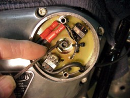
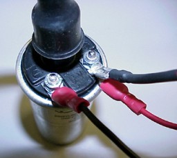
To individually check each coil, you will need to rewire the Boyer box wiring (black and red wires) so they go to one coil.
Positive Ground models: Run the black wire from the ignition box to the negative terminal of the coil. Run the red wire from the ignition box to the positive terminal of the coil. Run a ground wire from the positive coil terminal to a reliable ground (positive terminal of battery). It will look like the picture.
Take a spark plug out and lay it on cylinder head.
Kick over motor and check plug for spark.
Do the same for the other coil.
If either coil fails to fire, replace it or have it checked professionally.
Two of these Taiwan 6-volt coils in series will have approximately 3.8 ohms resistance.
Two 12-volt Taiwan coils in series will have approximately 9 ohms resistance.
Over tightening coil brackets may cause the coil primary windings to short (the meter will show a lower resistance than expected). This will cause the coil to draw a lot of current through the control box. It is common for the box to fail after such an event.
Testing the Battery
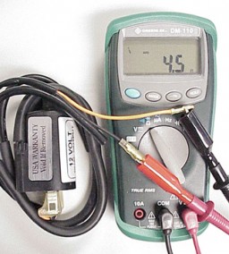
 If you don’t have access to either of the battery-testing tools shown, either the load or conductance type, you can still perform a basic battery test.
Before doing anything charge the battery until the voltage reading after resting for an hour or so exceeds 12.6 volts.
Connect a DC voltmeter to the battery connection posts and note voltage. If battery is fully charged it should read at least 12.6 volts.
Turn headlamp and brake light on. Monitor the battery voltage. The voltage reading will drop, but should not fall quickly. If it the headlamp bulb brightness diminishes and the voltage drops quickly to 12.4 or less you should have the battery professionally checked or replace the battery.
If you continue to have problems there are two professional testers. Battery testing has changed over the years:
Early testing was done checking the specific gravity of the battery fluid.
- Fully charged = 1.285 to 1.300
- Half discharged = 1.210
- Discharged = Below 1.150
This test was supplemented with a load tester, shown on the left of the two testers pictured, which measures the battery’s ability to provide current to the motorcycle electrics. The load test gives you a better idea how the battery will perform in real world conditions.
Current technology checks the condition of the battery by measuring conductance. Because the conductance of a battery can affect how an electronic ignition will perform, it is a better real world test for those vehicles. The meter shown on the right will give you a Pass – Charge – Replace reading.
When you are having problems with an electronic ignition the conductance tester provides the most reliable results.
If the battery fails any of these tests it should be replaced.
Alternator Rotors
While batteries can be a source of a lot of problems that plague electronic ignitions the alternator rotor can contribute to these problems. The magnets in alternator rotors degrade over time. It is the strength of the magnets magnetic field that determines how well it will maintain the battery. Also because it is the number of times, and the speed, as the magnetic fields pass through the stator windings that determines the output if there are fewer, weaker fields and the rpm of the engine isn’t high enough it will not produce enough electrons to keep the battery charged. When working on Lucas charging systems that the electrical system is balanced when the lights are on when the engine rpm is maintained over 3,000 rpm. Operating below that rpm for any length of time can permanently damage the battery and its ability to do its job.
Connections


A lot of Boyer problems can be traced to faulty or broken connections.
Pictured are four connectors in different conditions:
- The top connection almost guarantees you will have a problem;
- The second connection is better but shows only one crimp which only grips the bare wire;
- The third connection is better as there two crimps: one for the bare wire and one to grasp the insulation to prevent bending of the bare wire;
- The fourth has two crimps and short length of heat shrink tubing used as a strain relief. This the best way to secure the connections for your Boyer.
Some sources advise soldering the connections, but soldering has problems. Because a solder joint is rigid, the wire is prone to break where the solder ends. Also soldering makes it difficult to test and service the ignition system. Boyer does not recommend installing the ignition using soldered joints.
To prevent corrosion which can happen over time or when a connection is exposed to a lot of water spray, dielectric grease is recommended. It is available from several sources. Boyer Bransden recommends the use of dielectric grease on all electrical connectors, fuse holders and the battery terminals. It is not to be put on the connectors but used to seal the open end of connectors.
Corrosion at the wire connectors creates a high resistance connection. This causes voltage drops, which can cause the Boyer control box to appear to fail. Often what appears to be a Boyer failure can be traced to a corroded connection. Before assuming your Boyer has failed, pull apart and reinsert all of the connections used in your motorcycle ignition electrical system. Especially important to check are the connections for the Black/White and Black/Yellow wires.
Warnings and a review of things to check
- The black and white wires are connected together inside the box through a switching transistor. If one of these wires is connected to battery power and the other to ground, full battery current will go through the ignition box and will render the box junk!
- Battery faults: turn on headlight. It should remain bright for a minute or more. Voltage should not fall below 12 volts. If timing stays advanced and bike will not idle check condition of battery. This is where a conductance battery tester comes in handy. If the battery voltage drops to 11.8 volts, charge the battery and retest. If the battery will not hold 12.7 volts after charging and is below 11.8 volts it could be time for a new battery.
- Magnetic Rotor: Check to see if rotor has come loose in camshaft taper. Because of manufacturing variations in timing covers and camshafts be sure to check the clearance between the magnets and pick-up coil pins. Check to see if magnets will hold weight of rotor.
- Timing Plate: Check to see if resistance across the black/white and black/yellow is approx. 130 to 140 ohms (48 if it is for a Triumph or BSA triple). If it varies more than 10 percent or the meter indicates a wire is broken, replace the plate. Check with an ohmmeter to make sure there is no continuity between black/white or black/yellow wire and ground.
- Box: scratch the black/yellow and black/white lead coming out of ignition box together. You should see spark with plugs lying on head. Although a lot of Boyer ignitions will fire the plugs when you turn the ignition on and off, the Triumph and Norton twin ignitions do not have this feature. Turning the ignition on and off on these bikes will not typically (it will sometimes) fire the spark plug.
- Ignition switch, fuse holder, kill button, etc. can often be faulty or corroded: For testing run a jumper wire directly from the battery to the ignition box. Remember resistance in a circuit is additive. A little here, a little there and it adds up to a big voltage drop at the box. Running a wire directly from the battery eliminates any corroded connections or switches.
- Grounds: as above, for testing run a jumper from battery ground to the ignition box. Current thought by design engineers at Boyer is to run the ignition box ground directly back to battery. Read RF Whately’s articles about “single point” grounds here. Battery feed wires and battery grounds often fail. You can easily bypass the motorcycle feed (“hot”) and ground wires by running jumper wires directly from the battery to the ignition box. Be sure you have the wiring diagram at hand and make the connections to the correct wires.
- Do not assume engine is grounded to the frame, and thus the battery, Boyer ignition and coils. This is especially important when the frame is powder coated. If your wiring harness does not have a dedicated ground with wire going to the engine you will have to make one. The engine must be grounded to the same common point as the coils and ignition box.
- Plug wires: check the plug wires for continuity with an ohmmeter. If the ohmmeter shows that the spark plug wire has gone high resistance (above 5,000 ohms) it should be replaced. It is recommended to use metal core spark plug leads. Resistor spark plug wires are prone to breaking when flexed. If installed, and only the red box (Micro-Digital) and blue box (Micro-Power) require resistor plug caps, the cap resistance should be checked. The NGK plug caps should read 5,000 ohms with an ohmmeter.
- Coils: Check coil primary and secondary resistance. Compare results with manufacturer’s specifications. If the coil’s primary or secondary windings are “open” (broken internal wires) or the resistance reading is out of specification by more than 10 percent, replace the coil.
- Radio frequency emitted from alternator wires and spark plugs can interfere with the Boyer ignition box. The MKIII and MKIV (black boxes) are the least sensitive to RF interference. The Micro-Digital (red box) and Micro-Power (blue box) are both very sensitive to RF interference. It is strongly advised that RF canceling resistor spark plug covers (5000 ohm) be used with these units.
- Alternator wires should never be located near, or run parallel to, the timing plate wires, or battery ground or feed wires. For example: T160 wiring harness carries the alternator wires in the same wiring sub-harness with the wires coming from the timing plate. This will cause the bike not to start or run poorly.
- As voltage regulators fail they often leak alternating current. This AC leaking into the bike wiring harness can upset the operation of the Boyer and can actually cause the internal bits to be overloaded and fail. If you had an electronic box failure and you suspect that the regulator was at fault it is wise to check the voltage rectifier/regulator output for any stray AC voltage getting past the rectifier. It is best to do this using two batteries; one to run the ignition and one completely isolated to check the charging circuit output. With the bike running off the test battery, check for any leaking AC from the regulator by connecting the leads of a 100 volt AC meter to the second batteries terminals. It is common to see less than a volt AC, but if you are seeing 10 to 30 plus volts you must replace the regulator before connecting the output of the regulator to the same battery you are running the engine from.
- Never use an electric welder on any part of the motorcycle without completely disconnecting all wire connections from the electronic ignition box. If your charging system has a regulator that uses electronic devices to control the output or regulate the output, all of those connections should also be removed. Failing to do this will permanently damage the electronics inside the box.
- Always follow the wiring instructions to the letter. If the box does not work using wiring as described seek professional help. The black and white wires from the box are connected together through a switching diode in the box. If one of these is directly connected to the battery feed and the other to ground you will run full battery current through the box. It would be like dropping a wrench across the battery terminals. The wrench will fare a lot better than the little resistor that you will burn to a crisp. I cannot overemphasize that you should always follow the wiring diagram to the letter. We want to keep the smoke inside the box.
Checking for Voltage Drops
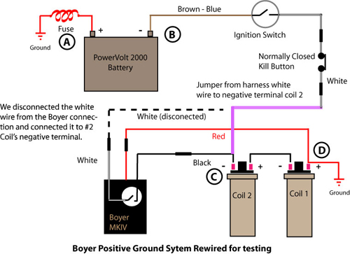
So we prepared the wiring to do a Volt Drop Test
To simplify the drawing we removed some wires from the diagram
We are showing the jumper connection between the kill button/Ignition switch and the negative terminal of coil 2.
1. Measure battery voltage across point A and B and write it down for reference.
2. Measure the voltage between point B and C. It should be the same as you read between A and B.
3. Read the voltage between B and D. It should read 0 volts.
If battery voltage across A and B less than 11.8 volts charge battery and load test. We want it to be 12.6 volts.
If voltage across B and C is less than battery voltage between A and B, one of the connections between the battery A and coil C is bad. Inspect and replace.
If voltage reading between B and D not equal 0 (zero) then you have a bad ground.
Note: If a volt meter isn’t handy you can use a head or tail light bulb wired so that you can reach battery and all of the connections you wish to check are within reach of the wires. Compare the brightness of the bulb connected directly across the battery with the brightness as you move one of the wires around the different measuring points. If at any point around the circuit the bulb dims you have a problem with high resistance connection, switch, fuse holder, ground, etc. which must be corrected.
For Those Who Choose to Wire Bike Negative Ground

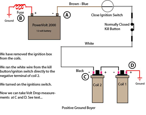
So we prepared the wiring to do a Volt Drop Test
To simplify the drawing we removed some wires from the diagram
We are showing the jumper connection between the negative terminal of coil 2 and ground.

1. Measure battery voltage across point A and B and write it down for reference.
2. Measure the voltage between point B and C. It should be the same as you read between A and B.
3. Read the voltage between B and D. It should read 0 volts.
If battery voltage across A and B less than 11.8 volts charge battery and load test. We want it to be 12.6 volts.
If voltage across B and C is less than battery voltage between A and B, one of the connections between the battery A and coil C is bad. Inspect and replace.
If voltage reading between B and D not equal 0 (zero) then you have a bad ground.
OK, I checked the voltage at the coil (C) and it is less than across the battery. What do I do now?
You have done a basic Volt Drop test on your battery and ignition circuit. For more information about the health of your ignition circuit you can take voltage measurements on either side of all of the components in the circuit. For example you can measure the voltage at the input terminal of the ignition switch and then move your meter lead and measure the voltage at the terminal where the voltage comes out. They should read the same. If the voltage coming out is less than what it was going in you have a high resistance switch. It will need to be replaced.
OK, I checked the voltage at the coil that is grounded and it is a couple of volts. What do I do now?
On most meters found in home workshops the voltage at the grounded coil terminal should read zero volts. If it reads more you do not have a good ground. Keep that one lead you had on the battery above and take the other meter lead and keep moving along the ground path. This could be a bracket the ground is attached to. Do this until the meter reads zero volts. This is true ground. It could be the ground wire is attached to an insulated battery box and it isn’t a real ground at all.
Checking your Boyer ignition should be easy. Refer to the following PDFs for things to check.
Triumph-BSA Twins MKIII, MKIV and Micro-Digital
Triumph-BSA Singles MKIII, MKIV and Micro-Digital
Triumph-BSA Triples MKIII, MKIV and Micro-Digital
Norton Commando Atlas MKIII, MKIV and Micro-Digital
Triumph-BSA Singles Micro-Power
Triumph-BSA Triples Micro-Power
Norton Commando-Atlas Micro-Power
Boyer Wiring
Copyright©John Healy 2007, 2008, 2009, 2010, 2011, 2012, 2013, 2014, 2015, 2016, 2017