Before we continue, in 1969 Triumph introduced an important change in how they sealed the pushrod tubes. They changed the pushrod tube to accept “O” rings at both the top and bottom. While if you read all of the Service Bulletins, and related articles, and mentally “connect the dots” it will tell you something important.
First Clue: What to look for is where they mention the depth of the groove in the tube for the bottom “O” ring. In later Bulletins they emphasize the importance to remove any sharp edges from the tappet block. Another Clue: They mention if the tube, with “O” ring installed, is not interference fit on the tappet on guide block or head you have the potential for a leak. The bottom “O” ring MUST be lubricated before installation! Because of variations in the dimensions with both the tappet guide block and the push rod tube’s “O” ring groove the interference fit can vary. We prefer P-80, or other rubber lubricant over grease, but in a pinch grease should work.
You see, what the engineers were thinking it would be i.d. and the o.d. of the “O” ring that would be doing the sealing at the tappet guide block. The seal at the top still relies on the crush to seal at the head. Being careful about the crush goes a long way to prevent excessive pushrod tube crush from bending the head.
Well at first, all these “improvements” didn’t work and they changed the compound on the top to a high heat “O” ring (71-1283) to made from Viton. The top 70-7310 ring was melting from the head’s heat. Then they reintroduced the bottom square ring (70-4752 – thick or 70-3547 – thinner) with a “wedding band” steel ring (71-1707) to provide some more seal at the bottom and a bit of crush on the top “O” ring.
The other thing they failed to consider was any variations in the critical diameters where the “O” ring had to seal. Things like the depth of the “O” ring groove in the tube, any variations in diameter of the tappet guide block, diameter of the tube itself at the top and the i.d. of the cavity where the top “ring” would be to big not letting the “O” ring to seal or too small where a sharp edge would sheer the o.d. of the “O” ring during installation.
All things to consider while the engine is on the work bench.
P-80 not only provides a VERY slippery condition. Being water based when it evaporites leaves the “O” ring in a better condition to effect a perfect seal. Or simply stated, “It really works!”
Triumph 650 and 750 Twin Push Rod Tube Crush
From the first day I read the phrase in an book by Mike Hailwood, “Dropping a piston circlip into the crankcase is a confounded nuisance” I knew exactly what it meant and how it applied to me. Let me explain: There are just some things in Triumph Workshop Manuals that never seem to be talked about, let alone explained. How to offer, and check the fit of, those pesky push rod tubes is just one. I guess it was something you were supposed to learn from your parents in your passage in to manhood. While they look benign, fitting them so they don’t leak, is just one of those nuisances.
Let’s explore some of the many possibilities to get this wrong:
First get some rubber lubricant called P-80. It is liquid based and once it does its job evaporates improving the ability for the “O” ring to seal. (several of the Dealers and web stores sell a small tube).
—The machining of the cylinder block itself for the tappet guide block hole. This one will get you frustrated right away and a problem shared with both original and replacement cylinders. Be sure to round the sharp edge in the cylinder casting so it won’t shear the “O” ring as you install the tappet guide block. P-80 works very well doing this job.
— If changing tappet guide blocks check the thickness of the tappet guide block shoulder where the lower push rod tube seal sits on.
—The overall length of the push rod tube.
—The depth of the machining of the head where it accepts the tube and its top seal. Also break the edge of the hole in the head casting for the “O” ring. The top “O” ring uses the o.d. of the “O” ring for the seal. It does not rely on the top and bottom of the “O” ring for a seal ( .020″ is plenty, if the surface of the sides of the hole in the casting are smooth and true. Any pushrod crush required is a lot less with “O” rings than that used with the earlier models with Square rings. Here you are looking for .020″ – .030″ crush.
—And the one that catches out even experienced mechanics not familiar with Triumphs: The cylinder head was bent and the head gasket surface has been machined in an effort to make a boat payment or an honest, but ill-fated, attempt to “make things right.” The head gasket surface is a datum point for the crush. Remove anything from this gasket surface and you immediately change the push rod tube crush for the worse.
Either too much “O” ring crush, or not enough can eventually lead to a bit of what the Brits call weeping or a good old American Texas gusher, with oil all over the motor. But before you start trying to solve oil leaking around the push rod tubes you must eliminate all of the other sources:
There is more to this job than the tubes, and their seal:
—Oil can be leaking from adjacent cylinder studs. Remember, some stud holes are open to the crankcase and should be sealed.
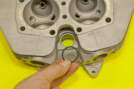
—Failed tappet guide block “O” rings, especially on models with oil fed tappets.
—And oil can migrate from the rocker box gaskets, and hardware, above. Gravity works when talking where is the oil coming from?
Taking time to locate the leak will save a lot of work and frustration.
Where do I begin?
The process starts when you remind the person doing your head work that you do not want him to machine anything from the head gasket surface. If the head gasket surface isn’t flat the head should be straightened. That nicely machined head might look good, but it is going to create more problems Down the Road than it solved.
The reason your head is bent in the first place is incorrect push rod tube “crush”. When the engine was assembled it was more than the recommended crush. Then the simple process of tightening the head bolts bend the head. If in an effort to provide a flat surface, more metal is removed it makes things worse. If corrective action isn’t taken the head will bend even more when it is offered.
Something even few “experienced mechanics” understand is just what happens to the concentricity of the valve seat is to the valve guide if the head bends as you tighten the head bolts. Triumphs are unique where the valve seat is cast into the head casting. Bend the head and you affect the concentricity of the seat to the centerline of the guide. If the person doing your work doesn’t understand this it is time to move on.
Any modern machine shop is familiar with straightening cylinders. Once the casket surface is straight one can lap the surface as necessary.

Early 650 head used through 1968
The recess in the head for the square
seal is 1.250″. The o.d. of the square
section mounted on the push rod tube
is 1.240″ +-.
Late 650-750 twin head used 1969-1982
The recess in the head for the “O” ring
is 1.140″ + -. There is a small step with a
small radius to align the “O” ring. The
o.d. of the “O” ring when mounted on
the tube is 1.200″ + -.

650-750 twin tappet guide blocks
Above:
Left block (70-1477) the shoulder is: 0.125″ 1/4″
Middle block the shoulder is: 0.1875″ 3/16″
Right block the shoulder is: 0.1875″ 3/16″
The outer diameter is: 0.9995″ to 1.000″
The hole in the cylinder should be: 0.999″
The angle of the hole is: 3.3°
Be sure to round the sharp edges of the block
to preventing them from shearing the “O”
ring!!!
If you have the cylinder off the engine you do not have to wait until the last minute to get all this right. All of the work can be done while the parts are on the workbench. Gather the cylinder, head, push rod tubes and seals and do a test assembly. Check the crush and make adjustments before you offer the cylinder to the engine.
So what is a convenient way to check the crush?
If you were like me trying to measure the “crush” is a bit of a conundrum. That is until I remembered a late 500 head gasket is .025 in. thick (it is close to the amount of crush I want to end up with — .030 in.). If I placed the 500 head gasket on top of the standard head gasket and then offered the head it should rock a bit and I can use a couple of feeler gauges to see if I am near the .030 in. I am looking for.
OK, I have more, or less, than the recommended crush!
If you have more than the .030 in. to .040 in. crush on a pre-“O” ring head (1968 earlier) where you should I look and how can I correct it?
First be aware that not all heads, push rod tubes or tappet guide blocks are compatible with each other. And because of production tolerances and different manufactures making all the bits it pays to check things.
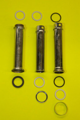
There are three basic designs:
You must select a head, push rod tube and tappet guide block that was designed to be used as a set!! I recently was offering a head to a 1965 650 where I had about .030” at the rear and near .080 in. at the front. It turned out that whoever installed the tappet guide blocks put one from a later model, with a thicker shoulder, in the front. I swapped out the offending tappet block and there was my .030 in. crush.
Where you can make adjustments:
The push rod (70-4752 – 70-3547 -n 70-1496) square seals come in various thickness and thicker head gaskets are now available. It could be a simple matter of changing to a thinner square “O” ring or installing an thicker head gasket.
Although there are times when the standard parts just don’t add up to the correct crush, but by far and away the most common problem is with a head that has been machined flat, rather than straightened. So in an effort to prevent push rod tubes from leaking we have examined all the parts to make sure they are all from the same style. Tappet guide blocks, push rod tubes and cylinder head must be all the same style.
We have checked the critical dimensions of all of the parts:
Thickness of cylinder block guide block shoulder, thickness of tappet block shoulder, length of push rod tube and thickness of cylinder head.
The shoulder on the base of the 650 cylinder, where the tappet guide block sits, is 51/64” thick. Given this dimension is given on the drawing as a fraction in machinist speak means a tolerance of +- .010 in.. This alone provides a .020 in. variation. In an effort to better control crush the 750 drawing has this dimension at + – .790 in. to .800 in.
Tappet Guide Blocks:
Over the years, with so many people making tappet guide blocks, you will find the thickness of the shoulder can vary. When you get a head where a lot has been removed for the head gasket surface you can machine as much as .020″ from the top of the tappet guide block.
“O” Rings:
You can juggle the thickness of the square section “O” rings to get the crush in line:
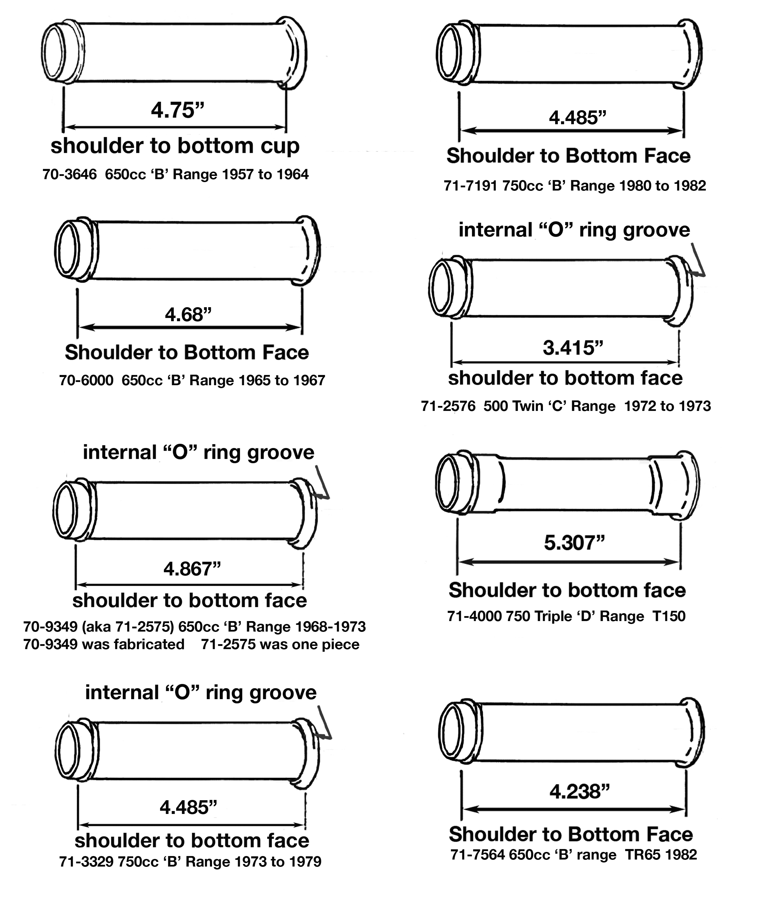
• The square section rings come in three thicknesses: 70-1496 @ 0.1875″ – 70-3547 0.093″ (3/16″) and 70-4752 0.125″ (1/8″).
• The round section “O” ring 70-7310 (Buna-n) and 71-1283 (High Temperature Viton aka Fluoroelastomer or FKM) are AS120. Nominal i.d is 1″ (0.987″) and a cross section of 0.103″ . When replacing the 70-7310 use a 71-1283
Note: The round section “O” ring was introduced in the 1969 model year. For a short time there was NO bottom square section “O” ring and “wedding band” used on the bottom of the tube. This led to oil leaks. When rebuilding a 1969 it is recommended that you install a 70-4752 square section “O” ring and 71-1707 wedding band.
Pushrod Tubes:
Other than swapping tubes, looking for ones that are shorter there is little opportunity to make adjustments with the push rod tubes. In fact there is very little variance between tubes.
Click on picture of pushrod tubes above!!
Cylinder Head:
As a rule the head itself should measure 2.755 inches thick (give or take as nothings perfect). There are two different head types to accommodate the two different push rod tube seals systems: early and late. The early head is machined for the flat “square section” ring. The late head has a deeper hole and machined to accept the “round section” “O” ring. Don’t laugh people mix this up! Even if all of the other parts of the equation are perfect, if the cylinder head is the wrong one, or the head gasket surface has been machined, you will have problems. While the head should measure x.xxx” after measuring heads over the years I have measured heads varying between 2.740” to 2.790″ thick (head gasket surface to rocker box surface).
Head Gasket:
If a lot of material has been machined from the head a thicker head gasket might be in order. It will make up for the missing aluminum and bring the compression back in line with today’s fuel. The standard 650 and 750 head gasket is .045” – .050″ thick there are special ones that are .080” and .100 in.. The head should measure +- 2.789” – 2.793″ thick (head gasket surface to rocker box surface)
I Don’t Use Oil or Grease to lubricate the “O” Rings:
While I have used motor oil to lubricate the round section “O” rings for assembly in the past I have become a believer that this can lead to oil “wicking”. Not a leak per se, but oil weeping around the seal. When I switched to using a rubber lubricant, like P-80, I noticed a much better seal. Many of the vendors on britbike.com sell a small tube of P80. It works wonders when working with rubber bits to ease assembly and the help create a leak proof seal.
copyright John Healy – Vintage Bike Magazine 2016 – 2026