

To use a modern voltage regulator the Miller generator must be rewired so it works like a Lucas generator.
Click on Link below to down load a printable PDF
millerconversion
Converting Miller Generator to Lucas Wiring
Rod Coates was pushing for a factory dirt track racer before the T120RT
Rod Coates was pushing for a factory built 500 racer before the AMA allowed 750cc engines to run professional dirt track. The T120RT was a skunk works operation that eventually cost him his job.
Click on the link below to view letter by Rod Coates to Tricor general manager, Earl Miller.
Triumph T120RT
Click on link to PDF below for more information on the T120RT:
Triumph T120RT – web
Valve Seat Information
Click on link below to download a PDF file containing installing valve seat information:
650-750head
Amal – A comprehensive look
AMAL Concentric Carburetors (updated to include Premiers)
I gratefully accept comments, and criticism. They can be sent to johntioc at aol.com.
THE BASICS:
Get comfortable, this will take time to read:
It’s the needle jet stoopid: (coined by Don Hutchinson who co-hosted many of my Tech Sessions.)
If there is one thing you come away with, from the time you spend reading this, is how import the needle jet is to every day performance of your motorcycle. To put this in perspective, a change in size of the needle jet’s metering orifice equal to 1/3rd the diameter of the average human hair, (one thousandths of an inch .001″) , will make the needle jet too rich or too lean.
In practice the typical 4 stroke needle jet’s orifice is .106″. A needle jet that has an orifice of .105″ will be too lean to a point where it could introduce unwanted detonation. A needle jet that has an orifice of .107″ will be too rich where it will significantly reduce fuel mileage and could foul the spark plug. The needle jet is in play in the throttle positions where we ride these bikes the most: closed to half throttle.
Another thing about the needle jet when you are experiencing problems at low throttle openings (below 1/4 throttle) is the size of the cross drilling located on the hex of the jet. The normal size is .035″. If it is smaller, or larger then .035′ it will change the amount of the fuel delivered significantly.
Caution: There are about ten odd people manufacturing needle jets around the world. When you see reference to using plug gauges to verify the needle jets size we are referencing checking new needle jets. Not all needle jets on the market have the jet orifice that is marked on the jet. The new .106 could have an orifice of anything but .106″. While you can get an idea if a needle jet is worn with an smaller than standard orifice plug gauge, it is better to routinely change them from a know supplier like Burlen.
Don’t underestimate the importance of the proper grade of the spark plug: You should tune to the manufacturer’s recommended brand and grade spark plug.
The grade of spark plug recommended by the motorcycle manufacturer is an important base-line for carburetor tuning. If you are fouling the recommended spark plug you should never change to a hotter grade plug in order to correct the problem. You do this with risk of causing severe damage to the engine.
The plug is not fouling because you have the wrong grade of spark plug.
All spark plug cross reference by brands are not always accurate for a particular motorcycle. After extensive testing at MIRA (UK vehical testing grounds) Triumph found that the NGK B8ES was not equivalent to the Champion N3. In the Triumph hemi-combustion chamber the B8ES was equivalent to a Champion N4. The B9ES turned out to be equivalent to a Champion N3.
With Amal, and most Mikuni carburetors, you are dealing with instruments that have multiple tuning stages. Typically it will be only one of these stages that is causing the problem of fouling a plug. This leaves the others to deal with the wrong grade plug. For example let’s consider a worn needle jet.
The needle jet’s orifice’s size will have its most influence below half throttle. Yes, that hotter plug will burn off the unburnt fuel from the plug below half throttle caused by a worn needle jet, but when you take the bike out on the highway, and running above half throttle, the fuel mixture will be too lean for that hotter grade plug. This brings you are one step closer to catastrophic destructive pre-ignition and detonation.
Add a few other factors like an abnormal increase in ambient air temperature, changes in barometric pressure, fill up with a tank of fuel where the octane rating is not up to snuff or you roll the throttle on without shifting down to drive up even a slight grade (effectively lugging the engine), and you are ever closer to that hotter plug causing expensive problems. You better hope your cell phone’s batteries are charged.
Note: Lugging is when you open the throttle and the engine doesn’t respond with an increase in rpm. A variable venturi carburetor relies on the incoming air’s velocity. The faster it passes through the venturi the more lift (vacuum) it develops. The more vacuum (differential in pressure between the venturi and atmospheric pressure) the more fuel will be drawn into the intake manifold. The difference in pressure is the result of the piston drawing in the air/fuel mixture as it descends down the cylinder bore. The actions of the carburetor and piston have a symbiotic relationship.
If the piston doesn’t pick up speed (increase rpm) as you open the throttle air velocity decreases. You are letting in more air with less fuel being drawn into the venturi. The air/fuel mixture becomes very lean. This dramaticaaly increases the chance you will suffer detonation, and or, catastrophic pre-ignition. Most of you will have heard about the SU carburetor. This design prevents you from lugging the engine. It is of a constant-depression design (often called Constant Velocity or CV). Another approach used before computers came into use is the vacuum operated shift mechanism. It shifted the transmission into a lower gear when the intake vacuum fell as you depressed the throttle. This was often miss-named a “passing gear.” Today the computer does all the thinking and with the transmssion having 6, 7 or more gears you hardly feel the transmission shift to a lower gear when the computer senses the engine is being lugged.
When I learned to drive Dad would palm slap the back of my head if I lugged the old Plymouth six. He was a field stone mason with hands the size, and strength of a gorrilla, but that’s another story. If you open the throttle, and there isn’t an immediate increase in engine rpm, that pinging (often unaudible) is telling you to shift!
My point here is with a standard engine, tune to the manufacturer’s recommended plug. They were not stupid. Be sure to mark your throttle so you know where to make your changes. But of course, if you change the compression, cam timing, etc. this must be taken into consideration when selecting the new plug, and jetting, you will be using, and that’s another story.
———————————————————
Do your home work before you start thinking about tuning a carburetor!
Be sure of the following:
All of the things will effect manifold vacuum as manifold vacuum directly effects how a carburetor works:
• New points and condensers are installed, and timing set.
• Manufacture’s recommended spark plugs are installed
• Valves are adjusted and bike passes a compression test. (Compression is very important when starting the engine.The incoming air/fuel charge must to be able to reach 140° F (temperature varies with the season) for the fuel to vaporize (reach distillation temperature) before the spark plug can ignite it. The ambient air temperature alone is not enough to get the fuel to 140° F. Compressing the incoming air/fuel charge provides the additional heat required to vaporize the fuel.
• If one is installed, the air cleaner is clean.
• Factory recommended jets are installed, and are not worn, corroded or damaged. I confirm their size before I install them.
• The float bowl gasket surface is flat, and not warped from over tightening.
If warped you will have an air leak breaking the fuel pick-up from the bowl for the pilot (idle carburetor) circuit.
• The fuel cap vent is clear, and there are no air leaks in the intake manifold or balance tube.
• The fuel taps, fuel line, fuel filter and fuel connections will flow enough gasoline.
• You know how to operate the choke. Yes, I am serious as this has been a problem in the past.
• You have installed new jets especially the needle jet.
• The fuel tank is free of rust! Very fine rust from the tank can block the fuel filter (causing a lean condition) and get under the float needle causing it not to seat (causing a very rich condition). There should be absolutely no signs of microscopic rust in the fuel!!
_______________________________________
When Tuning the Carburetor You Must Mark the Throttle.
While riding you have to be able to quickly, and safely, determine which one of the fuel circuits you are using at any specific time.
To tune the carburetor you MUST know where the slide is.
Is it?
• closed to 1/4,
• 1/4 to 1/2,
•1/2 to 3/4 or
• 3/4 to full throttle.
There are specific fuels circuits related to each of these throttle positions. Engine RPM or motorcycle’s speed have NOTHING to do with tuning a carburetor! For Example: If the problem you are experiencing is under 1/4 throttle it will not be the needle clip position or main jet (as long as the main jet is near, or prefereably, a bit richer than the recommended size for the bike you are working on). If the problem is between 1/2 and 3/4 throttle it is not going to be the position of the Pilot Air Screw or Slide Cutaway or Main Jet. Knowing the throttle position, and which fuel circuit services the carburetor at that point, will put you way ahead of someone who is using “Wild Ass” guesses. I cringe when I hear someone say referencing to their Amal or Mikuni VM, “My bike is running lean. I must need a larger main jet.” You should always ask yourself at what throttle opening is the bike running lean, then plan your moves accordingly.
Two Carburetors in One:
To better understand the Amal carburetor it is best to look at it as two carburetors ;
Idle and Main. The idle carburetor handles STARTING, idle and very low throttle opening. It is made up of the Pilot Jet (equivalent to the Main Jet in the main carb.) and Idle Air Mixture screw (equivalent to the slide in main carb.).
It is the Main carburetor that takes you from very low throttle openings right up through wide open throttle (WOT). The two carburetors each have a main jet and variable air supply while they share a common fuel supply.
The Idle Carburetor’s Pilot Jet is its “main” jet. The Pilot air Screw controls air flow drawing fuel from a shared float bowl. The fuel air mixture is delivered into a small mixing chamber under two Transfer Ports. The Transfer Ports are located each side of the back edge of the slide. They are the Primary, the smaller of the two (0.027″), located just behind the back edge of the slide and the Secondary, larger than the primary (0.040″), and located under the back of the slide.
• The typical Pilot jet in a 4 stroke version of the Concentric is pressed into the body. It is located behind the Pilot Air Screw and has a diameter of 0.016″ i.d.. A lot of people with Amal Premiers used on the Norton MKIII 850, with removable pilot jets are finding a .019″ pilot jet (622/502-19) works best.
• The pilot jet’s orifice is not a hole! It is a jet. A jet has a specific size. Poking something through it, or relying on ultra sonic or carburetor cleaner, will not work. If it is not cleaned to a specific size the bike will be hard, if not impossible to start.
• The Pilot Jet in a 2 stroke version is screwed into a threaded hole at the base of the main body. When the pressed in Pilot Jet has been enlarged by accident or on purpose, on some 4 stroke motorcycles (not triumph 500 Daytona), you can use the 124/026 two stroke jet screwed into the body.
• There are two small idle circuit transfer ports adjacent to the back edge of the slide. The smaller, Primary, transfer hole is 0.027″ while the Secondary is 0.040″.
• It is the Primary transfer port (smaller) that supports idle and transition between idle and main carburetors.
• The Secondary (larger) has two functions. At idle it feeds additional air into the mixing chamber. The change in vacuum as slide just lifts from idle reverses the flow through the Secondary port. It now instead of passing air into the mixing chamber it draws additional fuel into the venturi. This dditional fule helps to make the transfer from the idle carburetor to the main carburetor smoother. It is equivelent of the accelerator pump.
• The Slide Cutaway is an important adjunct to the Idle Carburetor and helps make the transfer from the Idle Carburetor to the Main Carburetor possible. If the carburetor will not take throttle from idle, and the engine stops running only to start again as you close the throttle, as you rotate the twist grip the slide is too lean. If it runs lumpy for a short time only to clean out as the slide is lifted it is too rich. The larger the cutaway the leaner the mixture will be.
• If the bike is hard, or will not start, or won’t idle it is quite possible there is something wrong with the Idle Carburetor. A blocked pilot jet is typical, but don’t overlook a blockage of the fuel passages or an air leak at the float bowl gasket because of a warped float bowl. Even very fine rust from a fuel tank can fill the fuel filter and block the flow of fuel. That fine rust can actually keep the float needle from seating.
• It is important that all jets and their orifices are clean and on size. These are jets, not holes.

The slide is in the idle position. The secondary transfer port under the back edge of the slide is taking in air into the small mixing chamber just under the two transfer ports. The fuel/air mixture that supports idle is ONLY coming out the small primary port just behind the back edge of the slide.

As the Slide is lifted: The Secondary transfer port reverses flow and is now drawing fuel from the mixing chamber adding to what is coming out of the main carburetor’s spray tube. It sort of acts like an accelerator pump in an automobile carburetor.

• A warped float bowl from over tightening the float bowl screws. The fuel supply passage for the pilot jet passes fuel from the float bowl to the main carburetor body through the float bowl gasket. If the bowl is warped the gasket will leak air into the pilot fuel passage. Fuel will not be delivered to the pilot circuit. If the bowl is warped it must be flattened, or replaced.

The pilot jet is pressed into the body. The arrow is pointing to the location of the .016″ pilot jet’s orifice. You can see the two air passages. One is in the center and leads to the needle jet. The other is at the top and leads to the pilot air screw and the fuel supplied by the pilot jet. The two transfer orifices, primary and secondary, are located the slot between the pilot jet and the tip of the pilot air screw.
NOTE: If the pilot jet is blocked the bike will not start. If it is not on size because of a partial blockage the carburetor will not respond to changes to the pilot air screw and idle will be erratic.
The pilot jet can be cleaned using a #78 drill (.016″ diameter). It will have to be securely mounted in in a brass tube or equivalent. It is a confounded nuisance when the drill gets stuck in the pilot jet and comes out of the brass tube! Twirl it between your fingers in a clockwise rotation and it will draw any “swarf” down stream of the fuel flow and help prevent the drill from becoming stuck.
Yes, a guitar string can remove “swarf” from the pilot jet orifice. It doesn’t insure the jet orifice is returned to its proper size. Also the “swarf” in the jet is pushed up stream of the flow of fuel. This allows the “swarf” to flow back into the jet and potentially partially block the orifice. The guitar string technique works only if you modify the carburetor where the body is drilled and tapped to accept a modified pilot air screw opposite the working air screw. This way you can push the “swarf” down stream of the orifice. See Amal’s web site to see this modification.
IMHO acetylene torch cleaning tips should NEVER EVER be used to clean the pilot jet. In an exercise to look into this I measured several that I had in house, and bought several new ones from “reliable” torch makers. Not one of them would clean a jet orifice and leave it anywhere near the original size. Most cut the orifice several thousandths oversize. Being such a small orifice small changes are significant to fuel flow.

You can clearly see the two pilot transfer holes. The Primary is the smallest at .027″, and closest to the reader. The Secondary is larger (.040″), and just behind the groove in the body for the slide. You can also see the brass “Straight Cut” spray tube.

There is an Important Difference Between Tuning the Mikuni VM and Amal Carburetors
• With Mikuni the tip of the needle never leaves the main jet orifice all the way through wide open throttle. Thus with the VM the needle is in play through wide open throttle.
• With the Amal, depending upon which groove the needle clip is in, the needle leaves the needle jet at approx. 3/4 throttle. It is no in play when tuning the main jet.
This chart is not drawn in stone. It is a representation of the different Amal fuel circuits, and at which throttle opening they are working. A version of this chart is often found on web sites. The usual problem with them is they have been copied directly out of the Mikuni VM manual and don’t represent Amal tuning.
Starting and ending throttle positions for each fuel circuit represented in this drawing are general representations and the actual ones can, and will, vary.

You will never understand how to tune an Amal, or a Mikuni for that matter, until you under stand the different fuel and air circuits and at what throttle opening they are in play. We often hear someone say, “My Amal (or Mikuni) is lean. I need a bigger main jet.” If you remove the main jet from the carburetor, the bike will still run normally until it gets above 1/2 throttle. As you see from the chart above the main jet doesn’t start to really come into any meaningful play until well above 1/2 throttle.
There are five individual steps to tuning:
• 1st in sequence- Full Throttle:
At full throttle you are working with the main jet.
If it is a stock bike use the main jet recommended by the manufacturer. If you have raised the compression start about three jet sizes larger than stock and work back down.
• 2nd in sequence- Idle:
At idle you are working with the pilot jet, pilot air screw. With most Amal’s you start with the screw out 1 1/2 turns from lightly seated.
• 3rd in sequence- 0 to 1/4 throttle:
At 0 to 1/4 throttle you are working with the slide cutaway, needle jet i.d. and pilot air screw. Typically a dual carburetor bike I will start with a # 3 and a single carburetor with a # 3 1/2 slide.
• 4th in sequence – 1/4 to 3/4 throttle:
At 1/4 to 3/4 throttle you are working with the needle jet just as the taper starts on the needle, taper itself and needle clip position. Without any information to work with start in the middle notch.
• 5th in sequence – Slide Cutaway:
Adjust the slide cutaway for a smooth transition from the idle to the main carburetor. IT It is not required to ride the motorcycle to adjust the slide. You should be able to turn the throttle briskly from closed and have the engine respond in kind.
Recommended starting main jets based upon Concentric 4 stroke by venturi:
622 22mm 120
626 26mm 140
627 27mm 170
928 28mm 180
930 30mm 200
932 32mm 220
1034* 34mm 360
1036* 36mm 370
1038* 38mm 380
* Out of production
NOTE: These are starting points and changes to the motorcycle will require attention to the main jet size. The wrong main jet can cause serious damage to the motorcycle and you! Check the manual that comes with the bike.
Tuning The Carburetor:
Too Rich Condition
• White Plastic Float Level Too High — Raise float needle seat in bowl.
• Stay-up Float Level Too High — Carefully bend the float tang.
• Old style white plastic float “Sunk” full of gas — Replace Float.
• Main Jet Too Large— Install lower number main jet.
• Slide Cutaway Too Low— Install slide with higher cutaway (# 2 is Rich while a # 4 is Lean).
• Needle Jet Too Large— Measure needle jet replace if worn, or if not worn, install needle jet with lower number.
• Wrong Needle Jet Type— Install correct needle jet.
• Needle jet cross drilled hole too small.
• Needle Clip Too Low— Raise Needle Clip to higher groove.
• Wrong Needle— Check motorcycle specifications.
• Wrong Spray Tube— Replace spray tube with leaner type – straight cut.
• Pilot Jet Too Large or Missing— Install smaller number jet.
• Pilot Air Screw too far In— Turn pilot air screw out.
• Choke On— Turn choke off.
• Fuel Leaking Past Float Needle— Fine rust in fuel – Clean fuel tank, filter and/or replace float needle.
Too Lean Condition
• Float Level too Low— Lower float needle seat in bowl.
• Stay-up float used with brass needle (use aluminum).
• Float Bowl Gasket Surface Warped— Replace or flatten surface.
• Main Jet Too Small— Install higher number main jet.
• Slide Cutaway Too High— Install slide with lower number.
• Needle Jet Too Small— Install needle jet with larger number.
• Needle Jet Cross Drilled Hole too Large— It should measure .035″ if larger replace needle jet.
• Wrong Needle jet type— Replace needle jet check spec’s.
• Needle Clip Too High— Lower needle clip to lower groove.
• Wrong Spray Tube— Replace spray tube with richer type: Stepped or slanted.
• Pilot Jet Too Small or Blocked— Clean or replace jet.
• Idle Fuel Circuit Blocked— Clean.
• Idle Transfer Ports Blocked— Clean.
• Pilot Air Screw Too Far Out— Turn screw in.
• Fuel Tank Cap Vent Blocked— Clean.
• Fuel Petcocks Too Small or Blocked— Clean or replace as necessary.
• Float Bowl Vent Blocked or Restricted— Open vent.
• Orifice In Float Needle Brass Seat Too Small— Replace with larger orifice.
TIP: If you have a stock 4 stroke bike kitted with Concentric carburetor of the proper size with a:
• 0.016″ (standard) pilot jet,
• 622/122 0.106″ needle jet,
• standard 622/124 2 ring needle in the #2 (middle) position,
• 3 1/2 slide if a single carburetor model,
• or 3 slide if a dual carburetor model,
• and main jet from the workshop manual.
You will be very close to perfect fuel air mixture in all 4 fuel air circuits. All you should have to do is some fine tuning like raising or lowering the needle or a slightly leaner or richer main jet.
The new Amal Premier Carburetor.
Tuning the Premier Concentric follows the same procedures as the earlier Concentric. There are a couple of things that are different. There is a new anodized aluminum slide. The cutaways match the earlier pot metal slide. The pressed in pilot jet is replaced with a new screw in jet. This jet allows easy changing, or cleaning. The standard Premier pilot jet is .017′ (2 annular lines). In spite of information on the internet, it is mostly Norton 850’s that work better with a .019″ (3 annular lines). The new carb comes with a new Stay-up float. Because of some dimensional changes from the original white plastic float they should be used with an aluminum float needle. Also these dimension changes require the top of the float be aligned with the top edge of the bowl.
Odd Stuff:

The tapered needle seldom wears to a point where it needs replacing. It can be easily measured on the part that will wear the most, the major diameter. You will find the diameter to be .0985″ (2.5mm). The needle grooves are numbered from the top down, with #1 being nearest the top. If the needle is bent it is a candidate to be replaced.
- NEEDLE PART NUMBERS
Monobloc—
• 375 models 375/063 stamped “B” on top 5 circlip grooves
• 376 models 376/063 stamped “C” on top 5 circlip grooves
• 376 BSA A10 376/096 stamped “C1” on top 5 circlip grooves• 376 models
RK6/116 stamped “C2” on to 5 circlip grooves
• 389 models 389/063 stamped “D” on top 5 circlip grooves• 389 models
RK9/088 stamped “D2” on top 5 circlip grooves
• 689 models as 389/063
Concentric—
600 Series:
• 622/063 One id groove- 2 stroke used with 622/079 needle jet, and 622/080 jet holder (600 series)
• 622/099 “Y” stamped at top – Alcohol needle
• 622/124 Two id grooves- 4 stroke use with 622/122 needle jet, 622/128 jet holder
900 Series:
• 928/063 Three id grooves- 2 stroke use with 622/079 needle jet, 622/080 jet holder (900 series)
• 928/099 “Z” stamped at top – Alcohol needle
• 928/104 Four id grooves- 4 stroke Developed for the 850 Norton
• 622/278 Five id grooves- T160 part of Trident lean kit
Mark II—
• 2622/063 2B1 – 2 stroke
• 2622/124 2A1 – 4 stroke – T140 use with 2928/122 .106″ needle jet
• 2622/125 2A2 – alcohol - • 2928/030 2C3 – 4 stroke- T140 EPA Tuning use with 2928/031 stainless .105″ needle jet
• 2928/063 2D1 – 2 stroke
• 2928/124 2D2 – 2 stroke
• 2928/125 2C2 – alcohol - • 2036/063 2F1 – 2 stroke
• 2036/077 2E3 – alcohol rich
• 2036/125 2E2 – alcohol

Checking new needle jets. Pictured is a minus .106″ plug gauge. It measures .1058″ and should be a slip fit in the needle jet orifice. A .106″ plug gauge would be a light press fit and a plus plug gauge (.1062″) would be a press fit. The small hole on the side of the hex is .035″.

This illustrates that the internal threads of the main/needle jet holder are counter bored.
The counter bore detail is especially important for the needle jet. If you look at the needle jet picture above you will see that the thread does not extend all the way to the shoulder. This a small, but important detail! If jet holder wasn’t counter bored the jet’s orifice would close up as you tighten the jet. Thus your .106″ jet would end up .105″ or smaller.
I mention this because a run of jet holders were run without the counter bore. When it was found out, instead of replacing the holders with proper ones, needle jets were supplied where the end of the thread was undercut. The thinking was the undercut would solve the problem. Well it didn’t, and as you tightened the jet in place it either broke off, or the orifice just below the undercut closed up as before.
The needle jet is the only jet that ISN’T identified by how much fuel it will flow. It’s orifice is measured in inches. The most common for four stroke engines is a 0.106″. The smallest needle jet is .105″. Below that the carburetor will rarely work. A few 4 stroke engines require a .107″, but they are few. Two strokes use larger needle jets as does carburetors set up for alcohol. An engine that runs well with a .106″needle jet will run lean with a .105″ and rich with a .107″. The needle jet is the only jet that gets larger in normal use and can wear to .107″, and beyond, in as little as 10,000 miles.
As the needle jet is the only jet in the carburetor subject to wear it should be at the top of the list for replacement at annual service intervals. A worn needle jet is so common that it led to coining the phrase “It’s the needle jet stoopid.”
Again a word of caution:
There are some ten odd people making aftermarket parts for Amal carburetors. Some like Keyster in Japan make some real nice jets. Others, including ones that were made in USA, UK and the Far East are poor copies, at best. Unless you are equipped to measure your new needle jet the most practical way to insure your new needle jet measures 0.106″ is to buy one in an Amal package.
Needle Jet Part Numbers:
Monobloc—
• 376/072 – state size: .105″, .106″, .107″ and up
Concentric—
• 622/079 2 stroke – state size: .106″, .107″, .108″ – and up. Not crossed drilled .714″ o.a. length counter bored .138″ at bottom – jet orifice opposite threaded end.
• 622/100 alcohol state size: .120″ and up
• 622/122 4 stroke state size: .105″, .106″, .107″, .108″ cross drilled .035″ hole – jet orifice at threaded end – .803″ o.a. length – counter bored .158″ deep at top
MKII—
• 2928/031 4 stroke stainless .105″ special T140 EPA bikes
• 2928/079 2 stroke state size: .105″, .106″, .108″, .109″ – up. Not crossed drilled – .770″ o.a. length – jet orifice opposite threaded end – counter bored .140″ deep at bottom
• 2928/100 alcohol state size: .120″ and up
• 2928/122 4 stroke state size: .105″, .106″, .107″, .108″ – up Crossed drilled with .035″ hole .860 o.a. length – counter bored .158″ deep at top. jet orifice at threaded end. Annular identifying groove at top.
- Needle Jet Notes:
Needle jets are the only Amal jet where the number refers to an actual inch dimension. The rest of the jets refer to flow in cc’s per minute. - Gasoline carburetors, both two and four stroke, are commonly fitted with needle jets ranging from .105″ to .107″. A .106″ needle is by far the most common one used. Needle jets mesuring .1065″ have been made.
- Alcohol carburetors are commonly fitted with needle jets .120″ or larger.
- Changing one size either way from the proper needle jet has a strong influence on just off idle to mid range running.
- A slightly worn, or oversize, needle jet will cause the motorcycle to run very rich at throttle openings up to approximately 1/3rd throttle.
- The crossed drilled hole in the 4 stroke needle jets can be made larger to lean out the mixture at low throttle openings. Enlarging this .035″ hole has the greatest effect while the straight portion of the needle is in the needle jets metering orifice. As little as .001″ increase in the size has an strong effect upon the amount of fuel the needle jet will deliver. The largest I have ever used is increasing the hole to .039″. As the hole approaches .050″ the carburetor stops working properly. To save embarrassment later, be sure to mark the needle jet as oversize.
- Enlarging the size of the crossed drilled hole can help clear up a bike that has megaphonitis. We found that 0.039″ cured megaphonitis on a Triumph 500 twin kitted with Triumph megaphones.
- You can use a reamer to enlarge a needle jet. If a .106″ is too small, and a .107″ large you can ream the jet .1065″.
- If you work on these carburetors as a part of your daily routine a set of Plus and minus .105″, .106″ and .107″ plug gages are handy.
Slide Positions:

Slide Closed (idle): (Red line on needle beginning of
taper. From the slide closed up to approx. 1/3rd throttle
the fuel metering is controlled by the i.d. of the needle
jet and the straight portion of the needle.

Slide at 1/4 Throttle: At 1/4 throttle the needle taper is
just beginning to leave the needle jet (as adjusted by the needle clip position).

Slide at 1/2 Throttle: At 1/2 throttle the fuel metering is
clearly being done by the needle’s taper.

Slide at Full Throttle: At full throttle the tip of the needle
is clear of the Needle Jet orifice. Depending upon which
needle groove the clip is in the Needle stops having any
effect around 3/4 throttle.
Float Bowls (with needle orifice by size):
Concentric—
• 622/052 .062″ float needle orifice – fuel pump – 2 stroke
• 622/054 .156″ float needle orifice – 2 stroke
• 622/055 .100″ 4 stroke – standard – drain plug type
• 622/056 .125″ 4 stroke – racing – drain plug type
• 622/057 .062″ drain plug type
• 622/058 .052″ 4 stroke – used with fuel pump
The float bowl drain was introduced in 1970.
MKII—
• 2622/055 .100″
• 2622/056 .062″ 2 stroke – fuel pump
• 2622/057 .125″ 4 stroke – standard
• 2622/058 .156″ alcohol
• 2622/059 .052″ 4 stroke – fuel pump
- Pilot Jets:2 stroke Concentric and MKII (also used as choke jets)• 124/026 in sizes 15-up in increments of 5cc flow (15 would flow 15cc per minute)
• 622/026-15 .014″
• 622/026-20 .015″
• 622/026-25 .016″ (standard to 600 and 900)
• 622/026-30 .018″ - • 622/026-35 .019″
- • 622/026-40 .021″Premier:
622/502 in sizes in increments of .002″
• 622/502-15 .015″
• 622/502-17 .017″ (Standard in 600 and 900 Premiers)
• 622/502-19 .019″ (common to Norton 850 Commando)
• 622/502-21 .021″
• 622/502-23 .023″
Slide Cutaways:
slides are listed from 2 to 4 in 1/16″ increments. The #2 cutaway would be 1/8″. A #3 cutaway would be 3/16″.
#2 = 1/8″
#2.5 = 5/32″
#3 = 3/16″
#3.5 = 7/32″
#4 = 1/4″
A note about slides:
The is a lot of folklore about the slide clearance in Amal carburetors. To insure the slide will not stick in the bore from the mounting hardware being over tightened the slides are given .0035″ to .004″ clearance. The typical comment is that Amal couldn’t hold a tighter tolerance. This is far from the truth. The early versions of the Amal Concentric had very close clearance and they experienced slides sticking when customers over tightening the mounting hardware. The .0035″ – .004″ clearance is intentional and the low throttle open jetting was compensated for the extra clearance.
Triumph 1979 T140 with MKII Carburetors update:
When using a MKII carburetors on a Triumph for off-road, or racing, it is possible to use European jetting. This jetting is for stock pistons and mufflers. Any modifications to compression or exhaust will require different jetting.
The Amal MKII is limited to 15° downdraft with the pilot jet in the bowl. If the downdraft is more than 15° you must move the pilot jet and blank jet. Put the blanking jet in the bowl and the drilled jet in the body. This similar to what you do with a MK1 1/2 when using the carburtor on a two stroke. Awitching the pilot jet’s location is a tuning trick for both 2 and 4 stroke tuning.
| Original EPA Jetting:
124/026 #25 Pilot Jet 124/0026 #50 Choke Jet 2928/031 .105″ Needle Jet 2928/060 #3 Slide 2928/030 2C3 Needle |
Suggested Non-EPA Jetting:
124/026 #15 Pilot Jet 124/026 #35 Choke Jet 2928/122 .106″ Needle Jet 2928/060 # 3 1/2 Slide 2622/124 2A1 Needle |
Part Numbers that are hard to find:
Welsh plug in bottom of Concentric body covering the pilot air/fuel mixing chamber 622/085
Pressed in pilot jet 622/107
Replacement float needle brass seat .100″ seating 622/099
T160 lean Kit: 622/278 Needle, 622/060 #4 slide
Tips for Racing Carburetors
There are occasions when you what to check an Amal pilot or main jet’s number against a standard.
Use these dimensions ONLY as a guide, as the final jet orifice is adjusted by hand during manufacture and checked with a manometer.
Flow in cc’s Jet Diameter
per minute in inches
15 –
20 .015″
25 –
30 .018″
35 –
40 .021″
45 –
50 .024″
55 –
60 .026″
65 –
70 .028″
75 –
80 .030″
85 –
90 .032″
95 –
100 .034″
110 .035″
120 .037″
130 .038″
140 .040″
150 .041″
160 .043″
170 .044″
180 .045″
200 .048″
220 .050″
240 .052″
260 .055″
280 .057″
300 .059″
Reference: – Vintage Motorcyclists Workshop by Radco page 129
Slide Cutaway and Straight vs Megaphone Exhaust Pipes:
Megaphone exhaust usually requires a main jet 40cc larger.
• Straight pipes typically use Leaner slide (higher #) slide like a #4.
• Megaphones typically use Richer slide (lower #) like a #2.
reference Tuning For Speed by P.E. Irving
GP Carburetor notes:
• GP limited to 20° down draft.
• GP2 introduced to allow greater down draft angles.
• GP pilot screw turns out to richen and in to weaken mixture.
• GP2 pilot screw turns in to richen and out to weaken
To allow greater down drat angles they moved the pilot air screw and pilot jet to the atmospheric side of the mixing chamber.
Tuning is the same as the GP except the pilot adjustment screws in to strengthen and out to weaken the mixture. This also cures pilot-jet weep at steep down-draft angles.
• Pilot jets are the same as used in the Monobloc (376/076).
• Fuel level in float is set to the bottom of the circle cut in the side of the air jet cover.
• The float bowl should be located in front of the main jet. This prevents fuel
starvation on acceleration.
• The GP relies upon an air-jet to correct fuel/air mixture while running on the main jet at a constant throttle opening (typically wide open throttle) subject to varying engine loads. As the engine load changes going over varying terrain, the air velocity through the venturi will change. As the air velocity changes so does the vacuum signal on the main jet. Without the air-jet, while climbing a grade, the air velocity will slow drawing less fuel and you will have a lean mixture. Going down the grade the air velocity will increase and draw more fuel giving you a rich mixture. The air-jet compensates for this change in air velocity at WOT providing a steady fuel/air mixture.
• The air-slide cab be helpful when tuning the GP, or TT. If at WOT the speed increases when the lever is closed slightly, the main jet is too small. If the speed falls off, the main jet is either correct or too large. The air-jet can be used to change the mixture to compensate for large changes in elevation or ambient air temperature during a race. This type of carburetor was designed for use in races venues like the Isle of Man.
• The air-slide, which controls the amount of air reaching the air-jet, is located on the side of the carburetor body. The air-slide cavity is easily recognized by the long slot on its side. Many people think the air-slide is a choke. The air-slide is opened and closed to change the amount of air reaching the air-jet.
• The purpose of the air jet is to compensate the mixture strength for varying air speed through the venturi.
• The air-jet for carburetor up to 1 1/16″ is .100″ over that it is .125″. The proper air-jet is installed at the factory and seldom needs to be changed.
Reference above:- Tuning for Speed by P.E. Irving
To read more about carburetors used on these motorcycles:
Tuning for Speed. by P.E. Irving
The Vintage Motorcyclist’s Workshop by Radco
Push Rod Tubes
Before we continue, in 1969 Triumph introduced an important change in how they sealed the pushrod tubes. They changed the pushrod tube to accept “O” rings at both the top and bottom. While if you read all of the Service Bulletins, and related articles, and mentally “connect the dots” it will tell you something important.
First Clue: What to look for is where they mention the depth of the groove in the tube for the bottom “O” ring. In later Bulletins they emphasize the importance to remove any sharp edges from the tappet block. Another Clue: They mention if the tube, with “O” ring installed, is not interference fit on the tappet on guide block or head you have the potential for a leak. The bottom “O” ring MUST be lubricated before installation! Because of variations in the dimensions with both the tappet guide block and the push rod tube’s “O” ring groove the interference fit can vary. We prefer P-80, or other rubber lubricant over grease, but in a pinch grease should work.
You see, what the engineers were thinking it would be i.d. and the o.d. of the “O” ring that would be doing the sealing at the tappet guide block. The seal at the top still relies on the crush to seal at the head. Being careful about the crush goes a long way to prevent excessive pushrod tube crush from bending the head.
Well at first, all these “improvements” didn’t work and they changed the compound on the top to a high heat “O” ring (71-1283) to made from Viton. The top 70-7310 ring was melting from the head’s heat. Then they reintroduced the bottom square ring (70-4752 – thick or 70-3547 – thinner) with a “wedding band” steel ring (71-1707) to provide some more seal at the bottom and a bit of crush on the top “O” ring.
The other thing they failed to consider was any variations in the critical diameters where the “O” ring had to seal. Things like the depth of the “O” ring groove in the tube, any variations in diameter of the tappet guide block, diameter of the tube itself at the top and the i.d. of the cavity where the top “ring” would be to big not letting the “O” ring to seal or too small where a sharp edge would sheer the o.d. of the “O” ring during installation.
All things to consider while the engine is on the work bench.
P-80 not only provides a VERY slippery condition. Being water based when it evaporites leaves the “O” ring in a better condition to effect a perfect seal. Or simply stated, “It really works!”
Triumph 650 and 750 Twin Push Rod Tube Crush
From the first day I read the phrase in an book by Mike Hailwood, “Dropping a piston circlip into the crankcase is a confounded nuisance” I knew exactly what it meant and how it applied to me. Let me explain: There are just some things in Triumph Workshop Manuals that never seem to be talked about, let alone explained. How to offer, and check the fit of, those pesky push rod tubes is just one. I guess it was something you were supposed to learn from your parents in your passage in to manhood. While they look benign, fitting them so they don’t leak, is just one of those nuisances.
Let’s explore some of the many possibilities to get this wrong:
First get some rubber lubricant called P-80. It is liquid based and once it does its job evaporates improving the ability for the “O” ring to seal. (several of the Dealers and web stores sell a small tube).
—The machining of the cylinder block itself for the tappet guide block hole. This one will get you frustrated right away and a problem shared with both original and replacement cylinders. Be sure to round the sharp edge in the cylinder casting so it won’t shear the “O” ring as you install the tappet guide block. P-80 works very well doing this job.
— If changing tappet guide blocks check the thickness of the tappet guide block shoulder where the lower push rod tube seal sits on.
—The overall length of the push rod tube.
—The depth of the machining of the head where it accepts the tube and its top seal. Also break the edge of the hole in the head casting for the “O” ring. The top “O” ring uses the o.d. of the “O” ring for the seal. It does not rely on the top and bottom of the “O” ring for a seal ( .020″ is plenty, if the surface of the sides of the hole in the casting are smooth and true. Any pushrod crush required is a lot less with “O” rings than that used with the earlier models with Square rings. Here you are looking for .020″ – .030″ crush.
—And the one that catches out even experienced mechanics not familiar with Triumphs: The cylinder head was bent and the head gasket surface has been machined in an effort to make a boat payment or an honest, but ill-fated, attempt to “make things right.” The head gasket surface is a datum point for the crush. Remove anything from this gasket surface and you immediately change the push rod tube crush for the worse.
Either too much “O” ring crush, or not enough can eventually lead to a bit of what the Brits call weeping or a good old American Texas gusher, with oil all over the motor. But before you start trying to solve oil leaking around the push rod tubes you must eliminate all of the other sources:
There is more to this job than the tubes, and their seal:
—Oil can be leaking from adjacent cylinder studs. Remember, some stud holes are open to the crankcase and should be sealed.
—Failed tappet guide block “O” rings, especially on models with oil fed tappets.
—And oil can migrate from the rocker box gaskets, and hardware, above. Gravity works when talking where is the oil coming from?
Taking time to locate the leak will save a lot of work and frustration.
Where do I begin?
The process starts when you remind the person doing your head work that you do not want him to machine anything from the head gasket surface. If the head gasket surface isn’t flat the head should be straightened. That nicely machined head might look good, but it is going to create more problems Down the Road than it solved.
The reason your head is bent in the first place is incorrect push rod tube “crush”. When the engine was assembled it was more than the recommended crush. Then the simple process of tightening the head bolts bend the head. If in an effort to provide a flat surface, more metal is removed it makes things worse. If corrective action isn’t taken the head will bend even more when it is offered.
Something even few “experienced mechanics” understand is just what happens to the concentricity of the valve seat is to the valve guide if the head bends as you tighten the head bolts. Triumphs are unique where the valve seat is cast into the head casting. Bend the head and you affect the concentricity of the seat to the centerline of the guide. If the person doing your work doesn’t understand this it is time to move on.
Any modern machine shop is familiar with straightening cylinders. Once the casket surface is straight one can lap the surface as necessary.

Early 650 head used through 1968
The recess in the head for the square
seal is 1.250″. The o.d. of the square
section mounted on the push rod tube
is 1.240″ +-.
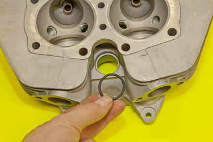
Late 650-750 twin head used 1969-1982
The recess in the head for the “O” ring
is 1.140″ + -. There is a small step with a
small radius to align the “O” ring. The
o.d. of the “O” ring when mounted on
the tube is 1.200″ + -.

650-750 twin tappet guide blocks
Above:
Left block (70-1477) the shoulder is: 0.125″ 1/4″
Middle block the shoulder is: 0.1875″ 3/16″
Right block the shoulder is: 0.1875″ 3/16″
The outer diameter is: 0.9995″ to 1.000″
The hole in the cylinder should be: 0.999″
The angle of the hole is: 3.3°
Be sure to round the sharp edges of the block
to preventing them from shearing the “O”
ring!!!
If you have the cylinder off the engine you do not have to wait until the last minute to get all this right. All of the work can be done while the parts are on the workbench. Gather the cylinder, head, push rod tubes and seals and do a test assembly. Check the crush and make adjustments before you offer the cylinder to the engine.
So what is a convenient way to check the crush?
If you were like me trying to measure the “crush” is a bit of a conundrum. That is until I remembered a late 500 head gasket is .025 in. thick (it is close to the amount of crush I want to end up with — .030 in.). If I placed the 500 head gasket on top of the standard head gasket and then offered the head it should rock a bit and I can use a couple of feeler gauges to see if I am near the .030 in. I am looking for.
OK, I have more, or less, than the recommended crush!
If you have more than the .030 in. to .040 in. crush on a pre-“O” ring head (1968 earlier) where you should I look and how can I correct it?
First be aware that not all heads, push rod tubes or tappet guide blocks are compatible with each other. And because of production tolerances and different manufactures making all the bits it pays to check things.
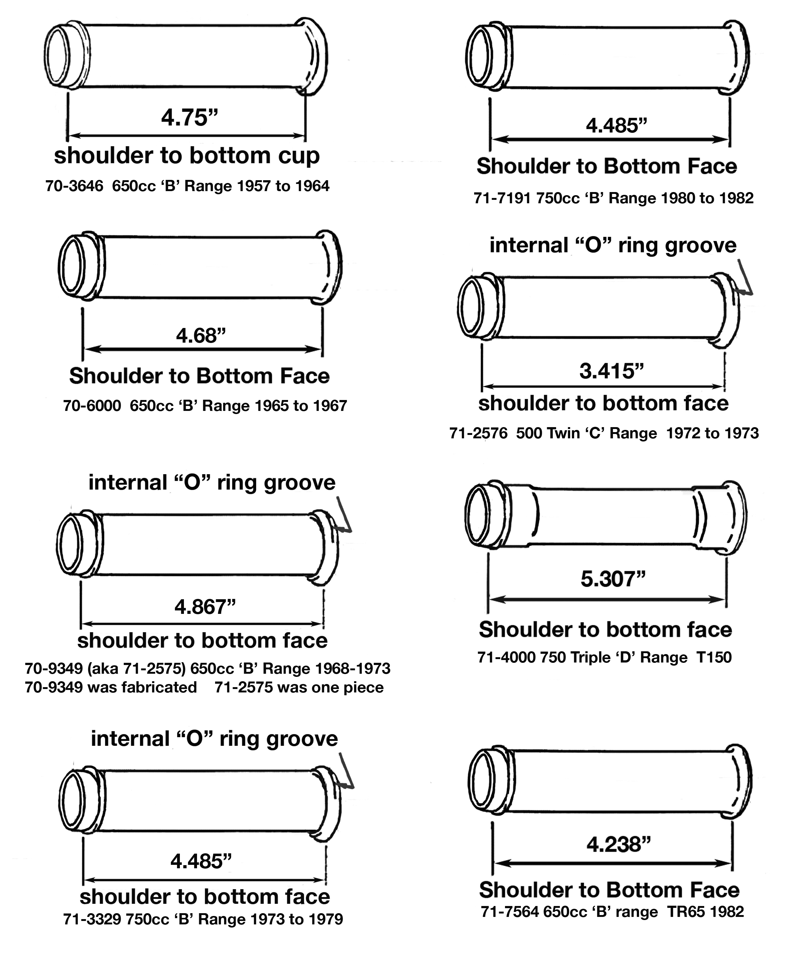
There are three basic designs:
You must select a head, push rod tube and tappet guide block that was designed to be used as a set!! I recently was offering a head to a 1965 650 where I had about .030” at the rear and near .080 in. at the front. It turned out that whoever installed the tappet guide blocks put one from a later model, with a thicker shoulder, in the front. I swapped out the offending tappet block and there was my .030 in. crush.
Where you can make adjustments:
The push rod (70-4752 – 70-3547 -n 70-1496) square seals come in various thickness and thicker head gaskets are now available. It could be a simple matter of changing to a thinner square “O” ring or installing an thicker head gasket.
Although there are times when the standard parts just don’t add up to the correct crush, but by far and away the most common problem is with a head that has been machined flat, rather than straightened. So in an effort to prevent push rod tubes from leaking we have examined all the parts to make sure they are all from the same style. Tappet guide blocks, push rod tubes and cylinder head must be all the same style.
We have checked the critical dimensions of all of the parts:
Thickness of cylinder block guide block shoulder, thickness of tappet block shoulder, length of push rod tube and thickness of cylinder head.
The shoulder on the base of the 650 cylinder, where the tappet guide block sits, is 51/64” thick. Given this dimension is given on the drawing as a fraction in machinist speak means a tolerance of +- .010 in.. This alone provides a .020 in. variation. In an effort to better control crush the 750 drawing has this dimension at + – .790 in. to .800 in.
Tappet Guide Blocks:
Over the years, with so many people making tappet guide blocks, you will find the thickness of the shoulder can vary. When you get a head where a lot has been removed for the head gasket surface you can machine as much as .020″ from the top of the tappet guide block.
“O” Rings:
You can juggle the thickness of the square section “O” rings to get the crush in line:
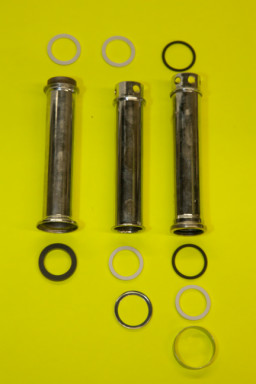
• The square section rings come in three thicknesses: 70-1496 @ 0.1875″ – 70-3547 0.093″ (3/16″) and 70-4752 0.125″ (1/8″).
• The round section “O” ring 70-7310 (Buna-n) and 71-1283 (High Temperature Viton aka Fluoroelastomer or FKM) are AS120. Nominal i.d is 1″ (0.987″) and a cross section of 0.103″ . When replacing the 70-7310 use a 71-1283
Note: The round section “O” ring was introduced in the 1969 model year. For a short time there was NO bottom square section “O” ring and “wedding band” used on the bottom of the tube. This led to oil leaks. When rebuilding a 1969 it is recommended that you install a 70-4752 square section “O” ring and 71-1707 wedding band.
Pushrod Tubes:
Other than swapping tubes, looking for ones that are shorter there is little opportunity to make adjustments with the push rod tubes. In fact there is very little variance between tubes.
Click on picture of pushrod tubes above!!
Cylinder Head:
As a rule the head itself should measure 2.755 inches thick (give or take as nothings perfect). There are two different head types to accommodate the two different push rod tube seals systems: early and late. The early head is machined for the flat “square section” ring. The late head has a deeper hole and machined to accept the “round section” “O” ring. Don’t laugh people mix this up! Even if all of the other parts of the equation are perfect, if the cylinder head is the wrong one, or the head gasket surface has been machined, you will have problems. While the head should measure x.xxx” after measuring heads over the years I have measured heads varying between 2.740” to 2.790″ thick (head gasket surface to rocker box surface).
Head Gasket:
If a lot of material has been machined from the head a thicker head gasket might be in order. It will make up for the missing aluminum and bring the compression back in line with today’s fuel. The standard 650 and 750 head gasket is .045” – .050″ thick there are special ones that are .080” and .100 in.. The head should measure +- 2.789” – 2.793″ thick (head gasket surface to rocker box surface)
I Don’t Use Oil or Grease to lubricate the “O” Rings:
While I have used motor oil to lubricate the round section “O” rings for assembly in the past I have become a believer that this can lead to oil “wicking”. Not a leak per se, but oil weeping around the seal. When I switched to using a rubber lubricant, like P-80, I noticed a much better seal. Many of the vendors on britbike.com sell a small tube of P80. It works wonders when working with rubber bits to ease assembly and the help create a leak proof seal.
copyright John Healy – Vintage Bike Magazine 2016 – 2026
Oil Leak – Crankcase not even
Checking crankcase mouth for step.

Checking crankcase mouth for step.
In the technical world we live in today imperfections are rare. In the day when these bikes were made they were common place. One that catches many mechanics out is a step between the two case halves. Sometime in the 1970’s someone at the factory decided that could speed things up by abandoning the time tested machining of the crankcase mouth with the cases bolted together. This gave us a perfect surface for base gasket to seal.

Checking with feeler gauge finding a .011″ step.
What it did give us was the potential for more oil leaks and distorting the cylinder bore. The first time the crankcase halves saw each other was at final engine assembly. As the pictures illustrate you can often find these 1970’s 650’s with a step between the case halves. This is guaranteed oil leak and/or a base gasket that is broken and sticking out of the joint. The only cure is to mount the case on a milling machine and fly cut the crankcase mouth. This will also cure another problem common on these twins: The crankcase mouth not parallel to the crankshaft center line. If you in search of some performance gain this is one of the first things you need to do to these 650-750 twin cases

Checking with micrometer finding the step is .015″ at joint.
While you are checking things:
Be sure to remove, and seal, the two studs where the stud hole goes right int0 the crankcase. Failing to do this oil will wick up the stud and leak oil next to the tappet guide block. With the common practice of over tightening the base nuts some aluminum around the stud can be drawn up above the gasket surface. This will also prevent the base gasket from sealing. Removing the studs and using a bastard file about 12″ long carefully draw file (google it) the protruding aluminum flush with the gasket surface.
Copyright John Healy – Vintage Bike Magazine 2015-2017
Changing Triumph 650 4-Speed to a 5-Speed
Update To A 5-Speed Gearbox
There have been many iterations of the Triumph 5-Speed transmission.
Not all 5-Speeds gear sets are the same. The early gear sets first offered in the 1971 model year turned out to be problematic. If used hard they would break. This wasn’t discovered during testing, but only after the bikes were in the field. When used hard, like when doing wheelies or drag starts, they would fail often breaking the crankcase in the process.
After a long wait for spare parts to repair all of the broken motorcycles sitting in dealer workshops, Triumph supplied an updated gear set under their part number CP-1000. The kit consisted of:
- 57-4661 Layshaft Dog
- 57-4654 Layshaft First Gear
- 57-4660 Layshaft Shift Fork
- 57-4653 Mainshaft First-Second Gear
- 57-4657 Layshaft Second Gear
- 57-4647 Layshaft Third Gear


There are still some early 5-Speed gear sets in 1971-1972 bikes that were never used hard and that are being used today. Just be aware that they still could cause problems. The gears included in the CP-1000 kit were finally incorporated in the 1973 model year production.

This is a picture of typical of the damage caused when the early gear set fails. I have seen much worse.
Tech Note: If a transmission gear includes a bushing the part number for the pair will be one number different than the number stamped on the gear.
Update Shift Quadrant and Plungers for a 5-Speed
When changing from a 4-Speed to a 5-Speed gear set there are a couple things you must remember to do. The gear selector quadrant in the outer cover and the index fingers must be changed to the 5-Speed parts. Also you need to enlarge the casting at each end of the mainshaft to allow mainshaft first and mainshaft high gear to clear.

The 5-Speed Quadrant pictured above right is wider limiting travel.

The plunger on left is an original 5-Speed plunger. Note the i.d. groove on the shaft. The 4-Speed plunger is on the right.

Again the 5-Speed plunger is on the left. This is an aftermarket plunger. Note: To make it interesting it does not have the i.d. groove. The 4-Speed plunger is on the right.
The 5-Speed Gear Set Assembly

Tech Note: There are several reason one or both of the shafts can be bent. A bent shaft will hamper the shifting. Also examine the gear dogs for wear. 5-Speed gear dogs are “back cut.” This means the more torque that is applied the tighter the gears pull together. It is normal for the leading edge of the dog to show a little wear. Excessive wear is a sign that something is wrong.
Tech Note: In the early layshaft the fixed high gear is just pressed on to the splines on the layshaft. This fixed gear has been known to move further onto the shaft locking the freely to rotate gear adjacent to it to the layshaft . This effectively puts the bike into two gears at once. As you would expect it starts to heat things up. The symptom is a difficulty to shift from gear to gear. The last iteration of the layshaft uses a circlip to retain the layshaft high gear in place.

Tech Note: There have been two iterations of the 5-Speed layshaft 1st shift fork. They are not interchangeable. The shift fork pins ride in the camplate grooves and are subject to wear. Also the forks themselves can be bent. If a fork is blued from heat where it rides in a gear it is a sign that the fork is bent, or the bike has been trying to jump out of gear. The gear and the fork should be examined and replaced as necessary.

Tech Note: There have been two iterations of the 5-Speed camplate. The one on the left is the will see most often while the one on the right is from a T160. The standard camplate can only be removed or installed after the mainshaft high gear is removed. The T160 camplate can be removed and replaced with the high gear in place. Because the T160 camplate is expensive, many technicians modify the early camplate to the T160 condition by grinding away a part of the camplate. When using the “full” round camplate you want to use the pointed plunger (57-7020 plunger, 57-4459 spring and 57-4400 housing). When using the lightened camplate you should use the rounded nose plunger (57-4226 plunger, 57-4459 spring and 57-4227 housing) from the T160. The T160 camplate has an ear that operates the neutral switch and might require attention to clearance when fitting.

Tech Note: The early layshaft high gear was prone to breaking. The gear was also noted for moving inward and keeping the adjacent 4th gear from rotating freely. The last iteration had the high gear widened and included a circlip to positively locate the high gear.

There have been several iterations of the high gear and its roller bearing. The first supplied under part number 57-4782 came as an assembly with Hoffman RL11V3M roller bearing. The high gear can be identified by the width of the roller race on the gear (see arrow above). It is 0.348″ wide and the rollers in the bearing are 0.345″ wide. Neither the gear or the bearing are available as replacement parts.
All of the later iterations of this gear use an RHP RJ009 roller bearing supplied under part number 60-4100. The race on the gear is 0.318″ wide and the roller is 0.3125″ wide. You cannot mix gears or bearings!! The last iteration of the gear is illustrated above with the “O” ring/lock tab groove at the end of the threads.
Tech Note: Even with the “O” ring in place gearbox oil can leak through the splines. Clean the splines with alcohol and apply your favorite sealant to seal the splines.

Don’t forget that you will have to enlarge the opening the bearing shield to 1 11/16″, or a bit more, where the 5-Speed high speed gear passes through the case. You will also have to enlarge the same shield behind the mainshaft bearing on the inner transmission cover to 1 1/8″. This allow the shoulder of the first/second gear cluster to clear the cover.

The last job is to replace the 4-Speed quadrant and replace it with the 5-Speed shown above. It will only go in one way and have the cotter pins line up. The teeth on the left engage the camplate and the notches on the right are used by the quadrant plungers to change gears.

Tech Note: 5-Speed mainshafts have been known to break. This is especially true for after market shafts. They typically break at the clutch end. Used on the street, the after market main shafts work fine. At the moment the only after market mainshaft that is avaiable it the last iteration and is made in Taiwan. But when setting up a bike for competition I always seek out a donor that was made at the Triumph factory.
Important Tech Note: There are two basic iterations of the mainshaft:
The early shaft (57-4432) used 9/16-18 tpi threads on the clutch side and 9/16-20 tpi on the kick starter side. These shafts proved to be very reliable both for the street and competition (especially the clutch nut, normally torqued to 70 foot pound is torqued up to 90 foot pounds). They work best when the taper is NOT lapped and the nut retained with Loctite.
The later shaft, first used in the TSS (57-7077), had larger threaded ends, but that said the only ones available are made in Taiwan. They have 5/8 – 18tpi threads on both ends. But here’s the catch: the depth of the 18 tpi thread on the kick starter end is so close to the cavity that retains the clutch rod bushing that it is very easy to break off the threaded end of the shaft. I still use 70 pounds on the clutch nut, but while 45 foot pounds is shown for the kick starter end nut, I prefer to under tighten it (30-35 foot pounds) and rely on the one place I would use red Loctite on a Triumph to retain the mainshaft kick starter nut. While perfectly OK for the street, I personally would not use one of these shafts on a competition machine. I would search out a donor factory 5-Speed shaft.
Indexing the Quadrant

You are are looking into the inside of the gearbox at the back of the camplate. The crankcase has been cutaway to provide this view. Note that the quadrant is indexed with the camplate’s teeth so the gear set will be in high gear. Look at this picture carefully because it is at the heart of understanding how to index the camplate and quadrant quickly and accurately. Notice that the quadrant is about one tooth away from hitting the top of the gearbox
The quadrant being one tooth away from being properly indexed is what you use as an aid to index the transmission first time, every time.
Assemble the gear set so that it is in 5th gear. Offer the inner cover with your thumb situated so you can push down on the quadrant. Once the inner portion of the quadrant clears the outer edge of the gearbox gasket surface push down with your thumb until the top edge of the quadrant is hitting the roof of the gearbox. Slide the outer cover assembly in until the two sets of teeth just begin to touch. To do this as I offer the inner cover I intermittently release the thumb pressure on the quadrant a little bit letting it start to fall. When it stops falling the teeth are just starting to touch. All you need to do now is to back the inner cover assembly just a bit which will allow the quadrant to fall. Then drop it one tooth and the gearbox is indexed.
How do I know it has dropped one tooth? When keeping a bit on inward pressure on the cover, as you lower the quadrant away from the roof of the gearbox tops of teeth are hitting each other which prevents the cover from going in. When the next set of teeth align the resistance pressure felt is gone you can now push the inner cover in place. The gearbox is indexed!
Quadrant in Fifth Gear

With the camplate rotated so the gear set is in 5th gear this is what you will see from the outside. Notice relationship of arrow to the quadrant’s teeth! So with some feel and the visual alignment of the quadrant’s teeth with the bushing you will index the transmission first time, every time.
Quadrant in 1st Gear

There are times when you want to index the gearbox with the gearset in 1st. This is especially true when indexing a transmission that has a leaf spring detent. The relationship of the quadrant and the floor of the gearbox casing is the same as with indexing in 5th gear. The proper alignment of the teeth is one tooth away from the bottom.
When indexing a leaf spring gearbox place the camplate and gearset in 1st gear. Then rotate the camplate counter clockwise past 1st gear so the 1st gear camplate indent is facing out at about the same level as the leading edge of the leaf spring. Offer the inner cover lifting the quadrant with your thumb it so it clears the gasket surface. Then let the quadrant drop to the bottom of the gearbox. As you slide the inner cover into place the tip of the leaf spring will engage the camplate indent and rotate the camplate into the proper 1st gear position. Do the opposite of what you did when you were in 5th. You are one tooth away and you need to raise the quadrant the one tooth.
Copyright John Healy 2015
Engines and Heat by Kevin Cameron
The familiar motorcycle engine is powered by heat, so a great many of its most difficult problems concern the management of heat and the results of high temperatures.
I like to construct word pictures for myself of what happens in engines, step by step. The reason I like to do this is that, unless I remind myself of what the underlying physical phenomena are, I can easily fall into accepting the validity of “the way it’s always been” without question.
INTAKE HEATING
Let’s begin with the intake stroke, assuming that our engine of interest is operating at or near peak torque. This means its cylinder filling is at maximum, so its heat release will also be maximum. Let’s also assume our engine has been running for some time, so the temperatures of parts have stabilized.
As the intake valve begins to open, some time before TDC, the piston is still decelerating, moving rather slowly. The exhaust valve is in the final process of closing, so at this point, the reflected low-pressure wave in the exhaust port arrives at the cylinder. It helps to pull exhaust product out of the small clearance volume above the piston (now at or very near TDC), and then it passes on through the intake valve, causing early motion of charge toward and into the cylinder.
The metals walls of the intake port are hot, and as the intake flow begins, this flow becomes turbulent, which accelerates heat transfer from hot metal walls to intake gas. As the flow nears the cylinder, it flows over the very hot intake valve, where it collects still more heat.
This heating of the intake charge both helps and hinders. It helps because this added heat evaporates any fuel being carried in the intake flow as droplets, or as a creeping liquid layer on the intake walls. Any fuel not evaporated by the moment of combustion passes through the engine unburned. Therefore a certain amount of intake heat, applied to evaporating fuel, is valuable.
On the other hand, we know that as the temperature of a gas rises, its density falls – it expands. For maximum power, we need maximum charge density in the cylinder. Therefore any intake heating reduces power by reducing intake density. This is why air-cooled engines develop better power on the first lap of a race than they do on lap five – the temperatures of parts are lower at the start, but rise toward steady-state values as the engine runs, causing loss of intake density through intake heating. Intake heating beyond what is needed to evaporate fuel is known as intake superheat and is always undesirable.
How much is the intake charge heated during intake? In an NACA paper from the late 1930s, this was measured in an air-cooled aircraft engine cylinder. Intake temperature rise in this engine was 75 degrees F! It’s hard to understand how this much temperature rise can occur as a gas flows only a few inches at high speed, but there are reasons for this. First, the metal temperature of the head of a hard-working air-cooled engine is very high. Second, the fast-moving gas flow is highly turbulent, constantly presenting a different part of the cool flow to the hot walls as the gas tumbles and swirls on its way. Turbulence promotes heat transfer.
HEAT AND DETONATION
There is a second reason why this gain in intake temperature is harmful to engine performance; it pushes the combustion process towards detonation. Detonation is auto-ignition and supersonic combustion of the last parts of the charge to burn, after the spark has ignited the charge in the normal way. As the flame consumes the charge, the hot, expanding burned gases compress the remaining unburned part of the charge. This heats it. In the unburned gas, this heat drives so-called “pre-flame reactions”. The hotter the unburned gas is, the faster these pre-flame reactions proceed. They are heat-driven chemical changes that break down fuel and air molecules, forming sensitive hydrogen-oxygen fragments called radicals. When the population of these radicals reaches a certain level, the gas of which they are a part ignites by itself, before the normal, spark-ignited flame front can reach them. Because these radicals are so chemically reactive, their combustion proceeds, not at the normal leisurely combustion rate of 50-150 feet per second, but at or above the local speed of sound. In hot gas, this speed is very high – thousands of feet per second. This shock wave, hitting the inside surfaces of the engine, makes the sounds we call ping or knock – detonation.
The hotter the intake charge is, the faster pre-flame reactions are driven, and the closer the engine is to detonating rather than burning smoothly and normally. Therefore intake charge heating is harmful to performance – especially if it goes too far. Anything that heats the intake charge makes detonation more likely. If an engine detonates at 12:1 compression, we reduce the compression until we find a ratio at which detonation ceases, and we lose the extra torque that this high compression gives us. If we could reduce intake charge temperature enough, we could accomplish the same thing – stopping detonation – without reducing compression ratio or losing torque. This is why highly-developed race engines always take their intake air from the coolest available source, and exclude hot air from radiators or cooling fins through the use of such things as intake airboxes.
REVERSE COOLING
This raises another point. We assume that cooling air should cool the exhaust side of the head first, because that maximizes the temperature difference between coolant (air) and the hot object (the cylinder head). Think again. Cooling air passes through the exhaust-side fins and in doing so becomes hot. Then it flows on, to the intake side of the cylinder head, and this hot cooling air heats, rather than cools, the intake side of the head. This heating causes excess intake heating and therefore earns us some power loss.
It is for this reason that modern liquid-cooled cylinder heads route the cooling water to the intake side first, then allow it to flow across the head to cool the exhaust side. This keeps the intake side cooler and thereby slightly boosts performance. Any for air-cooled engines? The last of the great air-cooled radial aircraft engines, the P & W R-4360, was also reverse-cooled, with the intake sides of its 28 cylinders facing the cool air, which then flowed around the cylinder to cool the exhaust side afterward.
EXHAUST VALVE TEMPERATURE
Back to the intake process. As the intake air enters the combustion chamber, it encounters the glowing, red-hot exhaust valve. This heats the intake charge even more. In the case of supercharged aircraft engines, with their large-diameter valves, exhaust valve temperature acted as an upper limit on engine performance. Push the compression ratio or the supercharger boost too high and the hot exhaust valve either pushed the charge to detonate or ignited the charge before the spark plug could do so (preignition). In either case, the engine was soon wrecked because preignition also leads to destructive detonation.
In smaller engines, the distance from the hot center of the exhaust valve, out to its rim of contact with the cooler valve seat is short enough to keep the valve temperature reasonable. In larger engines, the valves finally had to be internally cooled by partially filling a head-and-stem cavity with sodium. At operating temperature, the sodium became liquid and, sloshing back and forth between head and stem, carried excess heat out of the valve head, to the cooler stem. There, it could be conducted away into the valve guide. This in itself was a problem, because it caused oil in the guide clearance to coke, then seize the valve in the guide. During the early 1950s, Norton had to run a small exhaust-valve cooling radiator on its Manx racers, and BSA had to use a new, high-tech gas turbine alloy (Nimonic-80) in the exhaust valves of its Gold Star engines to prevent valve cupping from high-temperature creep. The bigger the valve, the worse the temperature problem it tends to have. This is especially so if the tuner has decided to use narrow exhaust valve seats – the narrower the seat, the hotter the valve will run.
Back to the intake process again. Not only does the fresh charge get heated by the hot exhaust valve, but also by the hot metal of the piston, combustion chamber, and cylinder wall. The better the engine cools, the lower will be the temperature of these parts, and so the cooler will be the final temperature of the intake charge. This in turn makes detonation less likely, allowing a higher compression ratio to be safely used, etc. If, on the other hand the engine is poorly cooled (like the rear cylinders of Harley-Davidson engines, or any cylinders which receive little cooling air), all its parts will run hotter,will heat the intake charge more, and will thereby be driven closer to detonating. You the tuner will then have to respond by reducing compression ratio, retarding spark timing, and/or using super-octane fuel to make the engine run without knocking itself to pieces. In air-cooled engines, cooling is a major key to performance; the cooler the engine can be made to run, the higher the compression ratio it will tolerate without detonating, and so the greater the torque it can safely make.
Once the intake process is finished, compression begins. The act of compressing a gas adds energy to it, and this energy appears in the form of a higher temperature. Therefore, the higher your engine’s compression ratio is made, the more the intake charge will be heated during compression. This is why a higher compression ratio pushes engines closer to detonation.
Finally, the spark jumps the plug gap and combustion begins. A swirling, shredding, mixing flame spreads away from the plug electrodes, driven by turbulence. Now we come to the question of flame speed. If the combustion chamber contains vigorous turbulent air motion, flame propagation will be rapid. Typically, for every degree of spark timing before TDC, combustion continues by a like about after TDC. This means that if your engine runs best with ignition timing at 32 deg. BTDC, its combustion process occupies roughly 32 + 32 = 64 crank degrees, centered on TDC. This in turn means that the slower your combustion is, the longer your piston and cylinder head are exposed to high temperature. This makes them run hotter, so they heat the next intake charge that much more, making detonation more likely. The longer combustion takes, the longer the last part of the unburned charge is exposed to heat, and the more likely detonation becomes for that reason also. Another reason favoring fast combustion is that mixture burned near TDC will generate higher pressure than will mixture burned when the piston is already well advanced into its expansion/power stroke.
COMBUSTION SPEED AND POWER
For these reasons, performance is better in engines with shorter combustion periods – that is, engines which make best power with smaller amounts of ignition advance. Unfortunately, tradition resists this idea. Even the language encourages them. Would you rather be thought of as advanced or retarded? Tuners know that more spark advance will often boost acceleration, so this makes running more advance seem desirable – the more you can use, the better. This leads to a general desire to run as much advance as possible, and the result is that some tuners are not upset when their engines need 38 degrees for best torque, or even 40 or more degrees. So much the worse for them!
If steps are taken to increase the turbulence of the intake charge, flame speed will rise, and the chamber will burn to peak pressure earlier. This requires the spark to be retarded so that peak pressure is again reached just as the piston is about to begin its rapid descent on the power stroke – at about 13-15 degrees ATDC. Likewise, if multiple spark plugs are used, the maximum distance of flame travel will be reduced – resulting again in being able to use less ignition timing, and often, in making more power. In one example – the Harley-powered BOTT special called “Lucifer’s Hammer”, the highest power resulted from a combination that gave best torque with an ignition timing of only 23 degrees BTDC. If you can build an engine that needs less ignition timing for best torque, it will in general make more power and run cooler than combinations that require longer timing.
Another way to add mixture turbulence is to raise intake velocity. Older tuners relied on the “hog ‘em out” school of porting, and engines inherited from such tuners often have huge ports. The current trend in engine porting is to use the smallest possible valves and ports. The resulting higher intake velocity puts more gas motion energy into the chamber, and this speeds flame travel.
During actual combustion, the burning of the fuel adds a large temperature rise to whatever the gas temperature was at the moment before ignition. That initial gas temperature is the result of;
a) the intake air temperature
b) the temperature gain of intake gas during the intake process
c) the temperature gain of intake gas during compression
Combustion is added on top of these other temperature rises, so the temperature during combustion is very high, and pushes heat into piston and cylinder head rapidly. Obviously, the higher any of these temperature gains becomes, the more heat is driven into head and piston. The two most important factors are the compression ratio and the degree of cylinder filling. If the engine breathes poorly, cylinder head temperature will be lower than if it breathes well.
As the crank turns, the piston begins its descent on the power stroke. As the piston drops, the gas above it is allowed to expand, so its pressure drops rapidly. By the time the piston has reached half-stroke, more than 80% of the power theoretically available in the combustion gas has been transferred to the piston. This is because near TDC, pressure is very high, while at 78-80 degrees ATDC, it is a small fraction (like 1/8) of its peak pressure. The second half of the power stroke produces little power, which is why opening the exhaust valve at 60 or more degrees BBDC doesn’t hurt performance.
This also explains why the cylinder head runs much hotter than does the cylinder. The head is exposed to peak gas temperature at about 15 degrees ATDC, but at this point, very little of the cylinder wall is exposed to the hot combustion gas. As the piston descends, exposing more and more cylinder wall, the gas temperature drops rapidly.
DETONATION AND TEMPERATURE
When an engine detonates – even slightly – its temperature begins to rise. This is because normally, internal surfaces are to a degree insulated by the layer of gas nearest them. Being mainly under the influence of the nearby metal wall, this gas, called the boundary layer, cannot move rapidly. Like the stagnant gas between the double glazing of a storm window, this boundary layer slows heat flow. But when deto begins, the shock waves of its sonic-speed combustion blast the boundary layer away, accelerating heat flow into head and piston. The hotter the internal surfaces of an engine become, the more the intake charge is heated, leading to detonation. This is a vicious circle that can rapidly destroy engines. Even light, intermittent deto causes a rise in engine temperature.
Most people are surprised to find that, when an engine begins to detonate, its exhaust gas temperature (EGT) falls. This is because, with more combustion heat being transferred to head and piston, there is less left over in the exhaust gas, so EGT falls.
COMPRESSION AND EGT
Now for another surprise. The higher compression is raised, the cooler the exhaust valve and exhaust pipe will run. We naturally assume that if we raise compression, thereby raising engine performance, we must also raise EGT. The reverse is true. Raising compression ratio does increase combustion flame temperature somewhat, but by expanding the burned gases more before the exhaust valve opens, it cools them more, thereby lowering EGT. Exhaust valves are heated by combustion gases during combustion, but they are heated even more by the high-speed, turbulent flow of exhaust gases past them after the valve opens. Because this is so, exhaust valve temperature is more closely tied to EGT than to peak combustion flame temperature. Harley tuner Don Tilley commented recently that at 11.5 compression, almost the entire header pipe of his Buell Harley engine became red-hot on the dyno. When he raised compression to over 13, only the first six inches of the pipe became red-hot. At the same time, this increase in compression ratio increased cylinder head temperature, because that is determined more by peak flame temperature.
HEAT FLOW TO THE EXHAUST PORT
It is a little-known fact that about half of the heat that flows into an engine’s cylinder head is picked up from the exhaust port. Why? Again, the reason is that the high-speed, highly turbulent exhaust flow is more efficient at transferring heat to cylinder head metal than is the slower, less turbulent flow in the combustion chamber during combustion. It is for this reasons that rational engines are designed with;
a) exhaust ports that are as short as possible, to minimise heat transfer surface area
b) steel stubs that extend as far as possible into the head, touching it as little as possible (preferably surrounded by an air gap)
Short exhaust ports obviously reduce the area of head metal exposed to hot exhaust gas. Lining as much as possible of the exhaust port with a steel stub, backed by an insulating air gap, further reduces the heat transferred to the head. In more recent times, tuners have the insides of their exhaust ports coated with insulating material such as zirconium oxide.
REDUCING EXHAUST PORT SIZE
In addition, engineers such as Jim Feuling have shown repeatedly that most engines do not need exhaust ports and valves as large as they have in stock form. Smaller ports of higher angle and more streamlined section flow just as well or better than stock size, and their smaller surface area further cools off high head temperatures. Again and again, better, smaller exhaust ports have reduced air-cooled engine head temperature by amounts large enough to permit safe use of higher compression ratio.
PISTON COOLING
How are pistons cooled? The answer is, by any means possible. In air-cooled engines, piston-to-wall clearances should be as small as possible, so that piston heat can easily pass into the cooler wall. Full-skirted pistons may be better in this respect than are the modern box-skirted variety. In some cases, three rather than the trendy two piston rings must be used – again, to promote heat transfer through that second compression ring. The less surface area of piston exposed to combustion heat, the cooler the piston will run, and that means, if at all possible to use the closest thing to a perfectly flat-topped piston. It is better to build compression by filling the head (provided that valve flow is not thereby impeded) than by building a steeple on the piston. The more surface area the piston has, the hotter it will run.
It is also valuable to place oil jets in the crankcase, aimed to direct oil onto the underside of the piston crown(s). Always remember that air-cooled engines need all the help they can get from oil cooling.
COATINGS?
What about thermally insulating coatings applied to piston, combustion chamber, and valve faces? This is an area for experiment, because the results are divided. Some find the coatings help with specific problems, like piston or valve distress. Others find that, because the coating surfaces run hotter than uncoated metal surfaces would otherwise be, they lead to detonation. Try it and see.
CAN AIR COOLING WORK?
Finally, how do air-cooled engines get rid of heat? This depends entirely on how much air passes through the fin space per unit time, and how much heat that air picks up in the process. In traditional air-cooled motorcycle engines, the cylinders just stick up like pieces of firewood, and whatever air enters the fairing and blows over them is all they get. Most of this air travels around the outside of cylinder fins, not through them, because this is the path of least resistance. Fins on cylinder heads are often blocked by rocker- or cam-boxes and pushrod or camchain tunnels. Cast-in cooling holes are often obstructed by casting flash, reducing their size and thereby cutting cooling airflow to the critical area between the valves. The result of all these limitations is high head and cylinder temperatures – unnecessarily high.
BAFFLES AND FORCED AIR
In air-cooled aircraft engines, finned cylinders are covered by baffles that force cooling air to pass only through the fin spaces. Air supplied to the fins is picked up in a region of high pressure, and hot air emerging from the fins is led to a region of lower pressure. It is this pressure difference that rapidly drives cooling air through the cooling fins. On motorcycles, the usual excuses given for not employing baffled cooling are that;
a) it won’t work
b) removing the baffles for service will take too long
These were exactly the excuses I heard for years, given for not employing intake airboxes on motorcycles. Yet every new bike sold now has just such an airbox, and gains significant power from its use. Just now at Daytona I saw more than one air-cooled motorcycle engine blow and blow again because it effectively had no cooling other than accidental. This is not necessary – air-cooling can work and work well, if anyone wants to apply established techniques to make it work.
Kevin