When a lower octane fuel with a higher volitility is better at controling detonation

VOLATILITY EFFECTS ON PERFORMANCE
    On the spec sheet issued by makers of racing gasolines, you will see volatility referred to twice; as the 10% point and the 90% point. The 10% point is that temperature by which 10% of the fuel has come over in the volatility test. This is a measure of the fuel’s ability to cold-start; the lower the 10% point temperature, the easier the cold-starting becomes. The 90% point is that temperature by which 90% of the fuel has come over. This is a measure of how easily or quickly the fuel as a whole will evaporate in a running engine. For example, two fuels of different 90% points may run identically in a 6000 rpm engine; both have plenty of time in which to vaporize adequately. Yet the fuel with the higher 90% point may chop a few hundred revs off the top of a 12,000 rpm engine.

    This effect is most often seen when a racer buys fuel by the 55-gallon drum, and leaves the drum open all the time he is at the track. Over time, much of the fuel’s front end evaporates, raising both the 10% and 90% points. Such a user often finds himself using stranger and stranger jetting as the drum gets down to the last third. Throttle response deteriorates and peak-rpm performance gets soggy. Finally, in desperation, he opens a fresh new drum and all his missing performance comes back. Keep race fuel capped and in a cool place. Every time you unscrew the cap and hear that “PSSHH”, that’s part of your volatility, throttle response, and higher-rpm performance escaping. If you are a small user of race fuels, buy in five-gallon tins instead of in drums – just as you would buy soda water in 8-10 ounce bottles instead of in liters, to keep it from going flat.

    In high-rpm racing engines, the time that elapses between the fuel’s entering the airstream and the spark that ignites the mixture is extremely short – sometimes too short for adequate vaporization. The result is lean mixture, just as in cold-starting. Trying to compensate by richening-up works, but it sacrifices power because the extra fuel passing through unburned robs heat from combustion. In some cases, a more volatile fuel can solve the problem (as above). Octane number is not the only important variable in racing gasoline. Look for a fuel with a lower 90% point and try it. Often, especially with two-strokes and their absurdly high compression ratios, a lower-octane fuel of a higher volatility will cause less knock than will a higher-octane fuel of lesser volatility. Failure to vaporize leads to leanness, which in turn can lead to knock.
A Favorite Subject
by Kevin Cameron

Lacing Norton Front Disc Rim – 06-1951

Where Do I Start?

wheel-building-034 The picture illustrates a rim pierced to accept a .300 inch nipple with a smaller .281 inch nipple installed. I show this because in the US .281 inch Japanese style nipples often find their way into spoke kits. It is possible this nipple could pull through during tightening, or fail in use, it is important to be sure you use the correct nipple for your rim.

wheel-building-038Modified Craftsman offset screwdriver (#41331) and my favorite Snap-On Spoke wrench (Snap-On #1351). You might have to file the opening a bit to get it to fit the spoke nipple.

wheel-building-035 A few minutes on a bench grinder, touched up with a file, and you have the perfect wheel building screwdriver. The tip secures the blade in the nipple and then pushes the screwdriver out of the nipple as the spoke hits it. It quickly threads all the nipples to the same depth.

06-1951dimple72

Click Pictures to Enlarge

Some Central Wheel Norton disc front rims (06-1951) are dimpled 3×1 and are handed. One dimple goes on the disc side and three dimples go on the non-disc side. Of the three dimples on the non-disc side of the rim, the middle one is for the disc side outside spoke (see above). In this picture the bottom is the disc side and the top is non-disc side of the rim.

This rim is handed: The three dimples in a row go on the non-disc side of the wheel. The single dimple goes on the disc-side.

The Offset: Based upon the WM2x19″ rim is offset is 1/2″ from the disc face of the aluminum hub to the nearest edge of the steel rim.

Lacing Norton disc wheels has always been a challenge. With the disc side spokes radiating out from hub to rim in nearly a flat plane, it is hard to get the rim offset correct. The disc side set of spokes, being nearly vertical to the hub provide very little sideways (axial) pull/force for the wheel builder to locate, and maintain, the rim’s offset as the spokes are tensioned.

Is there anything I should be aware of before I start? Yes, all 20 of the inside spokes, both disc and non-disc, have to be in place radiating in the right direction before you can offer the 20 outside spokes. These would be the Key Spokes for this wheel build.

Place the hub's disc side and the rim's single dimple side down.Where should I start? I kike to start with the 10 disc-side inside spokes. Place the rim (single dimple side) and the hub with the disc side facing the work bench.  Lift the hub and Insert the disc-side spokes into any one of the spoke holes in the disc side spoke flange. It doesn’t matter which disc-side hole in the hub you start with. Radiate them anti-clockwise. Leave a empty hole between each of these 10 spokes.

06-1951-72What’s next? You will have to determine which of the 20 non-disc side spoke holes to use to lace the 10 non-disc side spokes. If you were able to view all 40 of the spoke holes as if they were drilled in one flange you could number them in series 1 through 40. Lets move them apart as they appear in the hub. Counting clockwise from the disc-side inside spoke in hole #1, the non-disc side inside spoke will go into hole #2. You will have to weave the spokes around the disc side spokes and radiate these spokes clockwise. When you are done weaving the spokes around place it back on the work bench.

This spider web is made up of all 20 of the inside spokes. At this point you are ready to offer these 20 spokes to the rim.

If you did it right it will look like a spider web or a pile of sort-of organized twigs. At this point you will want to start offering the spokes to the rim. I start with the disc side inside spoke. Lay them so they are radiating away from the hub in an anti-clockwise direction. Then locate the single dimple on the disc side of the rim and thread a nipple onto each spoke.  To offer the non-disc side spokes look at picture below. Notice that the disc, and non-disc, spokes cross just before the reach the rim. The nipple hole just to the right of the disc side spoke is facing counter-clockwise and aimed at the non-disc side clockwise spoke. To do this they cross three spokes. Offer spokes to duplicate the pattern below.

06-1951offdiscinside

This is what your work should look like when all 20 of the inside spokes are in place. Notice how the spokes cross each other as they are laced into adjacent spoke holes.

conical one threadImportant Note: When lacing most wheels you first run the nipples onto each spoke until the end of the nipple is even with the end of the spoke threads. Not so with this wheel. You will only do that on the disc side spokes. On the non-disc side spokes you will leave 2 or 3 spoke threads showing. They will not be tightened until near the end of tensioning the spokes.

06-1951laced

Finish up lacing the 20 outside spokes. The disc-side outside spokes radiate clockwise and end up in the middle spoke hole of the three in line. The non-disc side pokes radiate anti-clockwise and go in the last open spoke hole. Remember, you are going to run the nipple up to the end of the spoke threads on the disc side, but leave 2 or 3 threads showing on the non-disc side. 

06-1951offsetThis is the point where you start truing (and get ready to establish the rim’s offset). These disc wheels are unique. You have one set of 20 spokes on the disc side that radiate out from the hub with little, if any, axial influence on the rim. These disc side spokes are nearly vertical. You have another set of 20 on the non-disc side that radiate out from the hub at an exaggerated angle that have more axial influence on the rim than ones on the typical wheel.

I like to do most of the actual truing of the rim, both axially (wobble) and radially (hop) while all of the nipples are free to turn with my fingers. With the normal rim this typically involves getting the offset right at the same time.

When you approach the job by getting the wheel true with the nipples finger tight, it makes it a lot easier to do finally truing. By doing the truing when the nipples are loose you will find the rim will be so close that it only has to be moved very little, often less than .020” during final tensioning. Approaching the job in this manner you will find that the hop is typically within tolerances (.010” to .015”), while you may have to adjust the nipples a bit to take remove any small wobbles. But with all this said, you will find this wheel a bit different. Remember, you always loosen first.

The typical wheel you will be trying to get the spoke tension equal on all 40 spokes. But this wheel is different with the radical different axial angles of the two sides; it is all but impossible to get spoke tension equal. The disc side will always have more tension than the non-disc side spokes. Depending a lot upon the stiffness of the rim it isn’t unusual to get the disc side spokes at 45-50 inch pounds while you will struggle to get the offset right and the non-disc side spokes much more than 25 inch pounds.

I start with working with just the disc side spokes. Begin by going around the rim taking a couple of half turns (half turns because the other spokes are in the way of you taking full turns) on all of the disc side nipples in succession. You go around taking a couple half turns on the nipple until some of the nipples start to touch the rim and the rim no longer shakes on the spokes. It’s the point where things start to come together and it starts to looking and feeling like a wheel. Usually it takes only 10 to 15 nipples coming up to the rim to make the rim stable.

More times than not at this point the rim will have very little hop and a little bit of wobble. Often you will find yourself loosening a couple of the nipples that came up tight and you can get the rim running very true.

At this point go around the rim and turn all of the remaining loose disc side nipples ONLY until they just come up snug to the rim.

What you want at this point is all 20 of the disc side nipples snugged up evenly (just past finger tight), the rim free of all hop with very little wobble, and all of the nipple tension even on all 20 spokes. You also want the rim offset as close to flush, or beyond, with the disc mounting face of the hub as you can get it. When you tighten the non-disc side the rim will be pulled back so you can set your ½” offset.

Brian Slark, Norton Service Manager claimed the wheel builders at the factory would put the disc side of the hub on the floor and stand on the edge of the rim. They did this to get the rim as far over to the disc side as they could. Now, go around the rim, taking a couple of half turns, until all of the disc side spokes are tight (45-50 inch pounds) while making small adjustments as you go to maintain the rim’s alignment.

Note: The disc side inside spoke, being near vertical, has no axial pull on the rim and will only influence the rim’s hop. But the disc side outside spoke crosses to the non-disc side of the rim and will provide a little axial pull on the rim. This tension will help pull the rim back toward the disc side helping you a little bit in maintain your ½” offset. When tightening I often favor the outside spoke a bit over the inside spoke to provide a little axial pull on the rim to the disc side.

At this point you want to finish tensioning the disc side spokes with a close eye on offset (depending on the rim 40 to 50 inch pounds). You also do not want any hop in the rim. It can wobble a bit, but no hop. You will find this easy if you keep all of the spoke tensions even.

The picture above shows a Norton rim with about 1/8″ offset (you want to end up with ½”) before I started to tighten the non-disc side spokes. You want to start with the rim as far away from its final offset position as you can get it. This is important because when you start tightening the non-disc side spokes, they will pull the rim back to, or past the 1/2″ offset very quickly.

Once you get to this point you can thread each nipple in turn on the non-disc side so they just contact the rim. There is no need to go round and round taking half turns. It is now just a matter of doing your final tensioning and truing of the non-disc side spokes – go easy you will never get the non-disc side spokes as tight as the disc side and maintain the 1/2″ offset.

Rim Offset:

1/2″ from the sprocket face of the aluminum hub to the nearest edge of the steel rim. Easy to say, much harder to do!


Building, truing and tensioning spoke wheels requires skills not normally acquired through normal daily living. It is beyond the scope of this document to supply you with all of the information, training and supervision to build a wheel properly. If you feel that you do not have the required skills, or do not have someone to check your work, seek out the services of a professional wheel builder. While not a difficult skill to learn operating a motorcycle with a improperly built wheel is dangerous and can lead to death, or worse!

Problems to look out for:

1. Many modern replacement rims are a lighter gauge
than the original Jones and Dunlop
.

Buchanan lists the spoke torque on the
insert in their spoke packaging as such:

“For large displacement cycles, the torque should be in excess of 80 inch
pounds. Hub and rim structure will determine the amount of torque that can be
exerted.”

The key to reading this sentence is the typical British rim is not considered for a “large displacement motorcycle!” Depending upon the rim you can only expect to use 30 to 50 inch pounds when you tension this rim. Because the original Dunlop and Jones rims are a lot stiffer than most aftermarket rims you can often exceed 50 inch pounds.  But don’t forget that wheels with cast iron hubs have been know to break if the spoke tension is too high.

2. One should be sure to lubricate the under
side of the head of the spoke nipple where it bears on the rim. This is especially
important when using stainless nipples
and or stainless rims. Stainless is prone to galling
and can actually bore a hole in the rim as you tighten the nipple. One must be extra careful when using stainless nipples in a stainless rim. Lubricate the parts well before assembly and stop if the spoke stops getting tighter as you turn it.

 Applying too much torque to a spoke can lead to rim failure. It is easier than you think to pull a nipple through a rim. Most British motorcycles are not considered A LARGE DISPLACEMENT
MOTORCYCLE
as described in Buchanan’s
instructions! The final torque using an aftermarket Triumph # 06-1951 rim would
be more like 35 to 50 inch pounds on the disc side. It can be a lot less on the non-disc side. This can be a little bit tighter if using an
original Dunlop or Jones rim.

Definitions:

Handed: Some rims are dimpled and drilled so that you can only put them on one way. The 06-1951 Norton disc is handed because of the 3×1 dimpling. The three dimples go on the non-disc side of the wheel. The early BSA front rim is handed because the angles the spokes enter the rim are at different angles for side to side. Most Harley rims are handed because you want the tube stem coming out on the non-sprocket side of the wheel. Many other rims are handed.
Key Spoke: The first of the ten spokes offered to this hub. They are key because they are the ones you must start with.
Cross Pattern: This wheel uses a cross three pattern on both sides.
Dimple: The bulge pressed into the rim to accept the nipple. This rim is what is called 2×2 where two dimples alternate from one side
to the other.
Piercing: The hole in the dimple for the nipple. There are three common sizes: .250″ and .300 used on British wheels and .281″ used on Japanese wheels. This rim is pierced .300″ and you must use a .300 diameter nipple.
Disc Side: The side of the hub where the disc is mounted.


Text and Pictures Copyright John Healy 1998-2015

Lacing Triumph 500 (1967 to 1974) and 650 (1967 to 1970) Front Wheel Rim (37-1230)

Lacing Triumph 500 (1967 to 1974) and 650 (1967 to 1970) Front Wheel (Rim 37-1230)

This also applies to the earlier 1963 to 1966 – all nail head hub.

You will need:

  1. A Triumph rim 37-1230, or equivalent, rim pierced to accept .300″ diameter nipples.
  2. A set of 40 spokes
    •   

    • a. Buchanan part #Tri712 (specify Chrome or Stainless spokes and nipples)
    • 10 spokes 4 3/4″ long with 95 degree head – Right outside  
    • 10 spokes 4 3/4″ long with 80 degree head – Right inside
    • 20 spokes 5 9/16″  long  with nail nead – Left side
    • 40 .300″” diameter nipples buchanan part number N10307
  3. Screw driver or modified offset-screw driver (picture below).
  4. Spoke wrench. 
  5. Nipple lubricant.

Where to Start:

  1. Verify that the holes pierced in the rims and the nipples measure .300.”
  2.    

  3. Using a .250″ nipple in a .300″ hole can lead to wheel failure!
  4. Lubricate the spoke threads using Buchanan’s lubricant.
  5.    

  6. Lubricate the head of the nipple on the edge that bears on the wheel rim.
  7. This rim is not handed.It can be fitted either way round.


This is a picture of a .250″ nipple in a .300″ hole. The nipple should fill the hole in the rim. Using a .250″, or .281″ nipple, in a .300″ hole can lead to wheel failure!

wheel-building-035

Modified “Speed Driver” and 8″ Spoke wrench. Both save time and make the job
easier, especially if your job is building wheels.

Three Types of Spokes used on the 1966-1970 Front Drum Wheel

37-1230-4

Three different spokes are used to lace this wheel. (left) Drum side outside spoke with 85° head. (middle) Drum side inside spoke with 90° head. (right) non-drum side spokes – nail head.

Where Do I start?

37-1230first

  • Click picture to enlarge


  • This is a pretty straight forward rim to lace.
  • You start with the hub flange side (brake drum side) and offer 10 of the 4 3/4″ x 80° spokes.
  • Notice the placement of the first spoke (indicated by the arrow) relative to the non-drum side nail head spoke holes.
  • The arrow sits between the two adjacent non-drum side hub spoke holes.
  • You would call this the key spoke for this wheel and must be offered first.
  • Offer the spoke to the rim and run its nipple on until the end of the nipple is even with the last of the spoke thread.
  • Got That One. What do I do next?

37-1230-2

  • Now you can put spoke set 2 and 3 in the opposite side.
  • These are all 4 3/4″ nail head and you simply push them through the hub.
  • Again, offer them to the rim and run the nipples until they are at the end of the threads.

Offering the last 10 spokes – Brake Drum Outside

37-1230-3 copy

  • Yes, I flipped the wheel over for this shot.
  • Next take the last 10 spokes (7  9/16″ – 95 degree head) and offer them like this.
  • Again, offer them to the rim and run the nipples until they are at the end of the threads.

The 37-1230 rim has 2×2 dimpling

37-1230rim 

 The preferred 37-1230 rim is a 2×2 dimple-piercing pattern. Two dimples on one side then two dimples on the other repeating around the rim.

Rim Offset:

The offset for the earlier 1963-65 non-flanged hub using all nail head spokes, and the later 1966-1970 (500 to 1974) flanged hub, is the hub’s brake drum side minus 1/64″ from the nearest side of the rim. Lay a straight edge onto the brake drum side side of the rim. You should be able to slip a .015″ (1/64″) feeler gauge between the straight edge and the side of the brake hub.

Problems to look out for:

1. Many modern replacement rims are a lighter gauge
than the original Jones and Dunlop
.

Buchanan lists the spoke torque on the
insert in their spoke packaging as such:

“For large displacement cycles, the torque should be in excess of 80 inch
pounds. Hub and rim structure will determine the amount of torque that can be
exerted.”

This hub and rim is not considered a “large displacement motorcycle!” Depending upon the rim you can only expect to use 30 to 35 inch pounds when you tension this rim. Because the original rims a a lot stiffer than aftermarket rims you can go to 40 to 45 inch pounds on original Dunlop or Jones rims.

2. One should be sure to lubricate the under
side of the head of the spoke nipple where it bears on the rim. This is especially
important when using stainless nipples
and or stainless rims. Stainless is prone to galling
and can actually bore a hole in the rim as you tighten the nipple. One must be extra careful when using stainless nipples in a stainless rim. Lubricate the parts well before assembly and stop if the spoke stops getting tighter as you turn it.

The key to reading this sentence is “Hub and rim structure will determine the amount of torque that can be exerted.” See the brake drum in picture below. The spoke tension broke the cast hub. While this happening is rare as the hubs age it is something you need to be aware of.

broken-drum-2
Applying too much torque to a spoke can lead to failure. While the nipple can
pull through the rim the cast hubs can also fail. This is a 1967-70 Triumph
front hub.

Triumph IS NOT A LARGE DISPLACEMENT
MOTORCYCLE
as described in Buchanan’s
instructions! The final torque using an aftermarket Triumph # 37-1230 rim would
be more like 30 to 35 inch pounds. This can be a little bit tighter if using an
original Dunlop or Jones rim.

Definitions:
Key Spoke: The first of the ten spokes offered to this hub. They are key because they are the ones you must start with.
Cross Pattern: This wheel uses a cross one on both sides.
Dimple: The bulge pressed into the rim to accept the nipple. This rim is what is called 2×2 where two dimples alternate from one side

to the other.
Piercing: The hole in the dimple for the nipple. There are three common sizes: .250″ and .300 used on British wheels and .281″ used on Japanese wheels. This rim is pierced .300″ and you must use a .300 diameter nipple. side is the left and timing side is the right side.


Text and Pictures Copyright John Healy 1998-2015
 

Harry Woolridge: Specifications 1938 to 1962

http://www.tioc.org/britbike/woolridge38to62.pdf

Boyer: How to troubleshoot a Boyer ignition

IMPORTANT

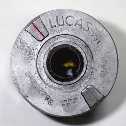
01_lucasrotorMost Lucas alternator rotors have timing marks, lines on the rotor, in two locations. These are a hold over from the ill fated Triumph Fury and BSA Bantam and its 180° crankshaft.

To set up your Boyer you will be using the full advance timing mark that aligns with the timing pointer when the piston is near Top Dead Center.

Remove the spark plugs and with the motorcycle on its center stand and in high gear, rotate the rear wheel until the piston or pistons are at Top Dead Center.

Then rotate the rear wheel backward a bit until the timing pointer aligns with the timing mark on the rotor. This will place the piston at Full Advance Before Top Dead Center. To make things easier in the future put a little nail polish in the groove that makes the line.

Now go to the other side of the motorcycle and align the small timing rotor screw head with the appropriate hole in the plastic plate. There is a hole for clockwise rotation (Triumph) and another for counter clockwise (BSA and Norton).

Mark this timing mark so you can easily identify it in the future.

If you are having problems getting a spark, even though the box is wired properly, check to see if the engine is grounded to the battery. The ignition box, coils and engine must share a common ground with the battery (or capacitor or Power Box if not using a battery). Do not assume that the engine is grounded by the mounting bolts!!

Start Diagnosing Problems with the Timing Plate
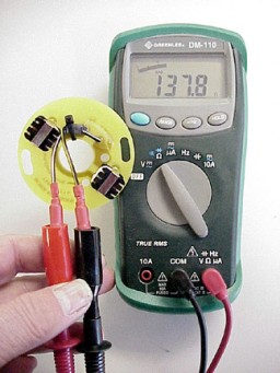
02_test137ohmConnect ohmmeter leads to Black/Yellow and Black/White wires as shown.

Turn the ohmmeter on and read resistance.

For a twin Triumph or Norton timing plate, typical resistance is 137 ohms. For a triple, typical resistance would be 48 ohms. These readings will varying depending upon the condition of the meter’s battery and the resistance of the meter’s leads. If the meter doesn’t “zero” when you put the leads together take that into consideration when you measure the coils resistance.

The resistance of individual coils should be approximately the same. If one coil measures 66 ohms the other should also measure 66 ohms.

If there is no reading on the meter or the individual coil resistances vary greatly or the reading is substantially lower than expected, this indicates a broken wire or coil wire insulation failure. Solution, replace the timing plate.

Scratching Control Box Leads

With the spark plug lying on the cylinder head, scratch the Black/Yellow and Black/White leads from the ignition control box together as illustrated. Please Note: This test assumes the battery, wiring, connections, switches and grounds are in working order.

03_boyerscratchAlthough a lot is attributed by other web sites to this test, it is possible for the box to be in perfect working condition and not produce a spark at the plug. If the battery, wiring, fuses, switches, grounds, ignition coils and Boyer control box are in good working order the spark plug should fire a series of rapid sparks.

If the spark plug doesn’t fire it could mean the ignition box has failed. But it could also mean the box is not properly wired into the motorcycle, you have bad grounds . the coil has failed, or the motorcycle electrical system is not able to supply enough electricity to run the ignition.

A compromised charging system, sulphated battery, corroded connections, corroded connections inside the fuse holder, corroded electrical switches or bad grounds cause more problems than failing boxes.

Turning the ignition switch on and off will fire the spark plug on most Boyer ignitions, but it will not always do this with Triumph/BSA and Norton ignitions. In these systems the box does not turn on until it receives a trigger voltage from the timing plate.

Rotor Magnetism

04_testmagnetHold each magnet of the rotor up to a wide flat surface (as shown). Each individual magnet should be able to support the entire weight of the rotor.

If either of the magnets will not hold the weight of the rotor, replace the rotor.

Loose Magnetic Rotor
05_testmaglooseMagnetic rotor has come loose in camshaft taper. Socket head bolt has broken loose or was too long and bottomed in camshaft before securing rotor.

Check socket head screw to see if it is tight. If it is tight and the rotor still turns freely, shorten the screw bolt. After making sure bolt is proper length, a drop of BLUE Loctite can be used to secure the screw. Tighten the allen screw.

The location, and depth, of the thread in the camshaft varies with cams made by Triumph and after market suppliers. The bolt is supplied to try to meet any condition in countered.

Never use RED Loctite in this application. If you do, you might live long enough to regret it.

Securing Wires

06_testtiewrapIf you experience broken wires, especially with a Norton, securing the wire leads to the plate securing stud with a small tie-wrap, as shown, will relieve the tension on the wire. On Norton, extra slack in the wire is required between the motor and the frame to absorb the movement of the isolastic motor mounts. With these models it is important to form a “J” loop with the wire where it goes from the motor to the frame.

Timing Plate Wires

07_testwiresThe polarity of the timing plate wires is important. The Black/Yellow and Black/White wires must be connected color to color. Make sure the Black/Yellow wire on the timing plate is connected to the Black/Yellow in the wiring harness and the Black/Yellow wire on the ignition box is connected to the Black/Yellow in the wiring harness.

If these wires are connected incorrectly, the ignition advance feature will not work properly. Also, the box will fire 70° from where you want it to. Instead of the ignition firing as the magnet approaches the coil pegs, it will fire the same distance after it has passed the coil pegs. Thus you would have to move the rotor in the camshaft 70° in the direction of rotation to get the timing correct. If you have to do this, it is telling you that you did something wrong.

• Most electronic ignition control boxes use a switching diode rated to handle 5 amps continuous.
• Remembering that Amps equal Volts divided by Resistance we can see if the coil, or coils resistance in series is less that 2.5 ohms the coils will draw more than 5 Amps.
• At 2 ohms the coils will draw 6 amps.

• If you have an EI box that fails it is important to check the coil, or coils in series, RESISTANCE before offering a new box.
• If the Boyer EI’s black wire, on a positive ground system, is accidentally grounded the box will be subject to full battery current. Effectively shorting the battery to ground through the switching diode. This puts the Amp draw through the switching diode over 12 amps.

The different male and female connectors on the Boyer EI box’s wires are arranged in such a manner to help prevent connecting the wires up the wrong way.  If you change the connectors it is in your interest to follow the same male – female pattern.

Doing a Quick Test.

You can run a jumper cable from the batteries positive and negative terminals directly to the EI box.

On positive ground systems run a jumper from the battery positive terminal to the coil terminal where the Red wire is connected. Run another jumper from the battery negative terminal to the White wire coming out of the EI box.

On a negative ground system run a jumper from the battery negative terminal to the white wire coming out of the EI box. Run another jumper from the battery positive terminal to coil where the red wire from the box is attached to the positive terminal of the coil. See wiring diagram for your bike downloadable below.

In both cases be sure to run a ground wire directly from the battery to the engine!

I this cures the problem see doing volt drop checks below to isolate the problem.

Checking Coil Primary Resistance

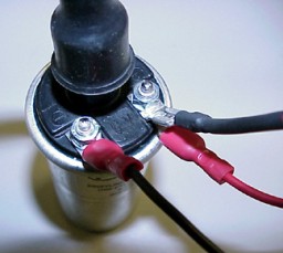
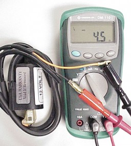
08_6vcoilEach 6 volt Lucas or replacement PVL coils will have 1.9 ohms resistance. If one, or both coils have a broken internal winding, zero ohms, you will not have spark.

Each 12 volt Lucas or PVL coils will have 3.8 ohms resistance

Primary and secondary coil resistance varies with the brand and model of coil. Refer to manufacturer for resistance readings of your coil.

The condition of the meter’s battery will affect ohmmeter readings. If there is any doubt about the condition of the battery it should be replaced before testing coils. To see typical coil resistances click here.

Checking Single Coil
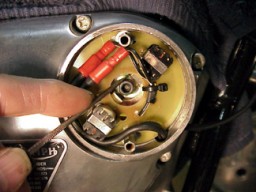
09_twinleadcoil
10_testcoilwiring

If the bike is running on one cylinder this is not a problem caused by the Boyer control box. Check each coil, plug wire, and spark plug individually.

To individually check each coil, you will need to rewire the Boyer box wiring (black and red wires) so they go to one coil.

Positive Ground models: Run the black wire from the ignition box to the negative terminal of the coil. Run the red wire from the ignition box to the positive terminal of the coil. Run a ground wire from the positive coil terminal to a reliable ground (positive terminal of battery). It will look like the picture.

Take a spark plug out and lay it on cylinder head.

Kick over motor and check plug for spark.

Do the same for the other coil.

If either coil fails to fire, replace it or have it checked professionally.

Two of these Taiwan 6-volt coils in series will have approximately 3.8 ohms resistance.

Two 12-volt Taiwan coils in series will have approximately 9 ohms resistance.

Over tightening coil brackets may cause the coil primary windings to short (the meter will show a lower resistance than expected). This will cause the coil to draw a lot of current through the control box. It is common for the box to fail after such an event.

Testing the Battery

11_testorsIf you don’t have access to either of the battery-testing tools shown, either the load or conductance type, you can still perform a basic battery test.

Before doing anything charge the battery until the voltage reading after resting for an hour or so exceeds 12.6 volts.

Connect a DC voltmeter to the battery connection posts and note voltage. If battery is fully charged it should read at least 12.6 volts.

Turn headlamp and brake light on. Monitor the battery voltage. The voltage reading will drop, but should not fall quickly. If it the headlamp bulb brightness diminishes and the voltage drops quickly to 12.4 or less you should have the battery professionally checked or replace the battery.

If you continue to have problems there are two professional testers. Battery testing has changed over the years:

Early testing was done checking the specific gravity of the battery fluid.

  • Fully charged = 1.285 to 1.300
  • Half discharged = 1.210
  • Discharged = Below 1.150

This test was supplemented with a load tester, shown on the left of the two testers pictured, which measures the battery’s ability to provide current to the motorcycle electrics. The load test gives you a better idea how the battery will perform in real world conditions.

Current technology checks the condition of the battery by measuring conductance. Because the conductance of a battery can affect how an electronic ignition will perform, it is a better real world test for those vehicles. The meter shown on the right will give you a Pass – Charge – Replace reading.

When you are having problems with an electronic ignition the conductance tester provides the most reliable results.

If the battery fails any of these tests it should be replaced.

Alternator Rotors

While batteries can be a source of a lot of problems that plague electronic ignitions the alternator rotor can contribute to these problems. The magnets in alternator rotors degrade over time. It is the strength of the magnets magnetic field that determines how well it will maintain the battery. Also because it is the number of times, and the speed, as the magnetic fields pass through the stator windings that determines the output if there are fewer, weaker fields and the rpm of the engine isn’t high enough it will not produce enough electrons to keep the battery charged. When working on Lucas charging systems that the electrical system is balanced when the lights are on when the engine rpm is maintained over 3,000 rpm. Operating below that rpm for any length of time can permanently damage the battery and its ability to do its job.
Connections

12_terminals
13_dielectric grease

A lot of Boyer problems can be traced to faulty or broken connections.

Pictured are four connectors in different conditions:

  • The top connection almost guarantees you will have a problem;
  • The second connection is better but shows only one crimp which only grips the bare wire;
  • The third connection is better as there two crimps: one for the bare wire and one to grasp the insulation to prevent bending of the bare wire;
  • The fourth has two crimps and short length of heat shrink tubing used as a strain relief. This the best way to secure the connections for your Boyer.

Some sources advise soldering the connections, but soldering has problems. Because a solder joint is rigid, the wire is prone to break where the solder ends. Also soldering makes it difficult to test and service the ignition system. Boyer does not recommend installing the ignition using soldered joints.

To prevent corrosion which can happen over time or when a connection is exposed to a lot of water spray, dielectric grease is recommended. It is available from several sources. Boyer Bransden recommends the use of dielectric grease on all electrical connectors, fuse holders and the battery terminals. It is not to be put on the connectors but used to seal the open end of connectors.

Corrosion at the wire connectors creates a high resistance connection. This causes voltage drops, which can cause the Boyer control box to appear to fail. Often what appears to be a Boyer failure can be traced to a corroded connection. Before assuming your Boyer has failed, pull apart and reinsert all of the connections used in your motorcycle ignition electrical system. Especially important to check are the connections for the Black/White and Black/Yellow wires.

Warnings and a review of things to check

  • The black and white wires are connected together inside the box through a switching transistor. If one of these wires is connected to battery power and the other to ground, full battery current will go through the ignition box and will render the box junk!
  • Battery faults: turn on headlight. It should remain bright for a minute or more. Voltage should not fall below 12 volts. If timing stays advanced and bike will not idle check condition of battery. This is where a conductance battery tester comes in handy. If the battery voltage drops to 11.8 volts, charge the battery and retest. If the battery will not hold 12.7 volts after charging and is below 11.8 volts it could be time for a new battery.
  • Magnetic Rotor: Check to see if rotor has come loose in camshaft taper. Because of manufacturing variations in timing covers and camshafts be sure to check the clearance between the magnets and pick-up coil pins. Check to see if magnets will hold weight of rotor.
  • Timing Plate: Check to see if resistance across the black/white and black/yellow is approx. 130 to 140 ohms (48 if it is for a Triumph or BSA triple). If it varies more than 10 percent or the meter indicates a wire is broken, replace the plate. Check with an ohmmeter to make sure there is no continuity between black/white or black/yellow wire and ground.
  • Box: scratch the black/yellow and black/white lead coming out of ignition box together. You should see spark with plugs lying on head. Although a lot of Boyer ignitions will fire the plugs when you turn the ignition on and off, the Triumph and Norton twin ignitions do not have this feature. Turning the ignition on and off on these bikes will not typically (it will sometimes) fire the spark plug.
  • Ignition switch, fuse holder, kill button, etc. can often be faulty or corroded: For testing run a jumper wire directly from the battery to the ignition box. Remember resistance in a circuit is additive. A little here, a little there and it adds up to a big voltage drop at the box. Running a wire directly from the battery eliminates any corroded connections or switches.
  • Grounds: as above, for testing run a jumper from battery ground to the ignition box. Current thought by design engineers at Boyer is to run the ignition box ground directly back to battery. Read RF Whately’s articles about “single point” grounds here. Battery feed wires and battery grounds often fail. You can easily bypass the motorcycle feed (“hot”) and ground wires by running jumper wires directly from the battery to the ignition box. Be sure you have the wiring diagram at hand and make the connections to the correct wires.
  • Do not assume engine is grounded to the frame, and thus the battery, Boyer ignition and coils. This is especially important when the frame is powder coated.  If your wiring harness does not have a dedicated ground with wire going to the engine you will have to make one. The engine must be grounded to the same common point as the coils and ignition box.
  • Plug wires: check the plug wires for continuity with an ohmmeter. If the ohmmeter shows that the spark plug wire has gone high resistance (above 5,000 ohms) it should be replaced. It is recommended to use metal core spark plug leads. Resistor spark plug wires are prone to breaking when flexed. If installed, and only the red box (Micro-Digital) and blue box (Micro-Power) require resistor plug caps, the cap resistance should be checked. The NGK plug caps should read 5,000 ohms with an ohmmeter.
  • Coils: Check coil primary and secondary resistance. Compare results with manufacturer’s specifications. If the coil’s primary or secondary windings are “open” (broken internal wires) or the resistance reading is out of specification by more than 10 percent, replace the coil.
  • Radio frequency emitted from alternator wires and spark plugs can interfere with the Boyer ignition box. The MKIII and MKIV (black boxes) are the least sensitive to RF interference. The Micro-Digital (red box) and Micro-Power (blue box) are both very sensitive to RF interference. It is strongly advised that RF canceling resistor spark plug covers (5000 ohm) be used with these units.
  • Alternator wires should never be located near, or run parallel to, the timing plate wires, or battery ground or feed wires. For example: T160 wiring harness carries the alternator wires in the same wiring sub-harness with the wires coming from the timing plate. This will cause the bike not to start or run poorly.
  • As voltage regulators fail they often leak alternating current. This AC leaking into the bike wiring harness can upset the operation of the Boyer and can actually cause the internal bits to be overloaded and fail. If you had an electronic box failure and you suspect that the regulator was at fault it is wise to check the voltage rectifier/regulator output for any stray AC voltage getting past the rectifier. It is best to do this using two batteries; one to run the ignition and one completely isolated to check the charging circuit output. With the bike running off the test battery, check for any leaking AC from the regulator by connecting the leads of a 100 volt AC meter to the second batteries terminals. It is common to see less than a volt AC, but if you are seeing 10 to 30 plus volts you must replace the regulator before connecting the output of the regulator to the same battery you are running the engine from.
  • Never use an electric welder on any part of the motorcycle without completely disconnecting all wire connections from the electronic ignition box. If your charging system has a regulator that uses electronic devices to control the output or regulate the output, all of those connections should also be removed. Failing to do this will permanently damage the electronics inside the box.
  • Always follow the wiring instructions to the letter. If the box does not work using wiring as described seek professional help. The black and white wires from the box are connected together through a switching diode in the box. If one of these is directly connected to the battery feed and the other to ground you will run full battery current through the box. It would be like dropping a wrench across the battery terminals. The wrench will fare a lot better than the little resistor that you will burn to a crisp. I cannot overemphasize that you should always follow the wiring diagram to the letter. We want to keep the smoke inside the box.

Checking for Voltage Drops
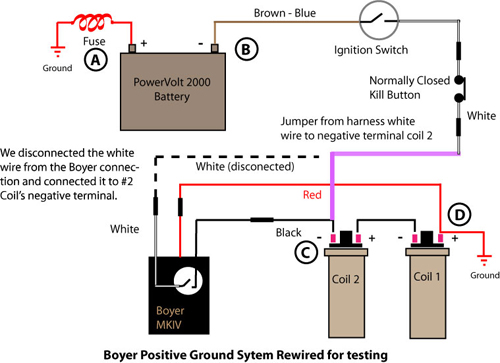
14_voltagedropposweb1


So we prepared the wiring to do a Volt Drop Test

To simplify the drawing we removed some wires from the diagram

We are showing the jumper connection between the kill button/Ignition switch and the negative terminal of coil 2.
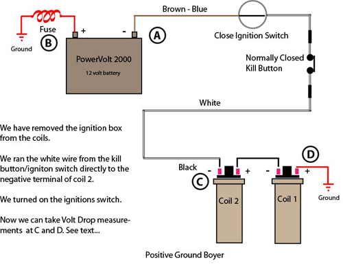

voltage drop copy

1. Measure battery voltage across point A and B and write it down for reference.

2. Measure the voltage between point B and C. It should be the same as you read between A and B.

3. Read the voltage between B and D. It should read 0 volts.

If battery voltage across A and B less than 11.8 volts charge battery and load test. We want it to be 12.6 volts.

If voltage across B and C is less than battery voltage between A and B, one of the connections between the battery A and coil C is bad. Inspect and replace.

If voltage reading between B and D not equal 0 (zero) then you have a bad ground.

Note: If a volt meter isn’t handy you can use a head or tail light bulb wired so that you can reach battery and all of the connections you wish to check are within reach of the wires. Compare the brightness of the bulb connected directly across the battery with the brightness as you move one of the wires around the different measuring points. If at any point around the circuit the bulb dims you have a problem with high resistance connection, switch, fuse holder, ground, etc. which must be corrected.

For Those Who Choose to Wire Bike Negative Ground

16_voltagedropnegweb1

So we prepared the wiring to do a Volt Drop Test

To simplify the drawing we removed some wires from the diagram

We are showing the jumper connection between the negative terminal of coil 2 and ground.

voltage dropnegativeground copy

1. Measure battery voltage across point A and B and write it down for reference.

2. Measure the voltage between point B and C. It should be the same as you read between A and B.

3. Read the voltage between B and D. It should read 0 volts.

If battery voltage across A and B less than 11.8 volts charge battery and load test. We want it to be 12.6 volts.

If voltage across B and C is less than battery voltage between A and B, one of the connections between the battery A and coil C is bad. Inspect and replace.

If voltage reading between B and D not equal 0 (zero) then you have a bad ground.

OK, I checked the voltage at the coil (C) and it is less than across the battery. What do I do now?

You have done a basic Volt Drop test on your battery and ignition circuit. For more information about the health of your ignition circuit you can take voltage measurements on either side of all of the components in the circuit. For example you can measure the voltage at the input terminal of the ignition switch and then move your meter lead and measure the voltage at the terminal where the voltage comes out. They should read the same. If the voltage coming out is less than what it was going in you have a high resistance switch. It will need to be replaced.

OK, I checked the voltage at the coil that is grounded and it is a couple of volts. What do I do now?

On most meters found in home workshops the voltage at the grounded coil terminal should read zero volts. If it reads more you do not have a good ground. Keep that one lead you had on the battery above and take the other meter lead and keep moving along the ground path. This could be a bracket the ground is attached to. Do this until the meter reads zero volts. This is true ground. It could be the ground wire is attached to an insulated battery box and it isn’t a real ground at all.

Checking your Boyer ignition should be easy. Refer to the following PDFs for things to check.

Triumph-BSA Twins MKIII, MKIV and Micro-Digital

Triumph-BSA Singles MKIII, MKIV and Micro-Digital

Triumph-BSA Triples MKIII, MKIV and Micro-Digital

Norton Commando Atlas MKIII, MKIV and Micro-Digital

Triumph-BSA Twins Micro-Power

Triumph-BSA Singles Micro-Power

Triumph-BSA Triples Micro-Power

Norton Commando-Atlas Micro-Power

Boyer Wiring

RF Whatley

Copyright©John Healy 2007, 2008, 2009, 2010, 2011, 2012, 2013, 2014, 2015, 2016, 2017

Cam timing and the meaning of life

by Kevin Cameron

Cam timing is not identical with the meaning of life, but to hear people talk about it you might think it was close. Actually, cam timing is a purely technical matter, and is based upon ordinary discoverable physical phenomena. It can be understood!

The first question to be tackled is total cam duration. This choice depends upon the engine’s intended use, as you can see from the language used in cam-grinders’ brochures. Some decoding is in order.

The first part of the decoding has to do with reducing BIG NUMBERS to something that actually means something. We Americans like big numbers, and cam-grinders oblige by adding in the duration of their clearance ramps to make cam profiles look longer. The clearance ramp is a zone of very low lift rate, intended to take up valve clearance gently before the cam begins to seriously accelerate the valve up off its seat. On the closing side, the ramp takes care of putting the valve back on its seat at a velocity low enough that the valve will not (a) bounce a lot (they do bounce on seating) or (b) hammer the seat or cup the valve.

Since these clearance ramps involve only tiny amounts of lift, they give an exaggerated idea of what the actual flowing valve duration is. To get a better idea, look at “timing measured at 1.0-mm checking clearance” or, if you have the cam at hand, measure it yourself with that .040” or 1.0-mm clearance. At one millimeter of lift, some useful flow may take place, so this is arbitrarily chosen as a means of getting a better idea of actual cam duration. In car cam catalogs the checking clearance may be .050” because auto engine valve lifts are so large. The bottom line is, never let yourself be impressed by valve timings exaggerated by the addition of the clearance ramps. Always look for timings at .040” checking clearance.

Next you must decode the cam descriptions in the makers’ literature.
“Streetable mid-range boost” generally means this cam has near-stock duration but increased lift. Such a cam will have a wide usable torque range – something that comes in handy in racing. The reason the Honda RC211V has been so successful in MotoGP racing is not trick electronics – it is because this motorcycle has torque everywhere and is easy to ride.

“All-out power for Bonneville and high-rpm drag use” means the cam has its duration extended so far that at lower revs the piston has plenty of time to pump much of what has been sucked into the cylinders back out again before the intake valves close. You should take this description to mean ‘useless but interesting’. Uncounted numbers of novice engine builders have been sucked into buying these paperweights because they mistakenly think that horsepower can win races. Have a look at the Aprilia in MotoGP – impressive steam down the straights, but never in the top-10. Motorcycles spend their on-throttle time accelerating, and that means they benefit from having high torque averaged across the rpm range actually used. In other words, if you race on a track that requires use of first gear, and you have a normal 1st-to-2nd rev drop of 25%, you absolutely must have a cam that will pull across the top 25% of your rev band. If you don’t, you will find yourself stuck on the exit of that 1st-gear turn with your engine making a weak, hollow sound just below its usable torque while your competitors howl or bubb off into the distance ahead of you. Believe me, you won’t reel them back in down the next straight. They are gone.

The concept of seeking maximum torque as an average across the rpm range actually used is worth emphasizing again. Almost nobody does this because we are all so easily hypnotized by BIG (as opposed to useful) numbers.

“Streetable but increased higher-rpm punch”. This may be the one. It’s a toss-up with “Streetable mid-range boost”.

You must also consider that four-valve engines require less total cam duration than do two-valve designs. This is because initial flow area is total valve perimeter multiplied times lift, and because the four-valve with its small valves can lift them faster than the two-valve can (think of valves as floppy parasols – the bigger the parasol, the more it flops). This means the four-valve develops flow area faster than a two-valve, and thus needs less total duration for the same flow. Read through the cam catalogs to get an idea of representative numbers.

Legend says that back in 1980 American Honda had cams made for its 1025-cc fours in increments of 5-degrees of duration, then tested every cam to grind their way doggedly to an optimum. By contrast, Rob Muzzy said in 1982, “Nothing new has come along in cam design for the past 25 years, so it makes sense to pick a reasonable number (total duration) and then work with it. Adapt the cheap, easy-to-change parts (exhaust pipe, intake lengths) to the expensive hard parts (cams). Not the other way around.” As I recall, Muzzy had a fair amount of success.

Next you have to decide how to time the cams you plan to use. Because there are many cam durations, it is best to use the cam lobe center as a means of thinking about this.

We determine piston top dead center by setting the piston at X mm BTDC (by use of a long-reach dial gage or piston stop), noting the number on the degree wheel, then setting the piston at X mm ATDC, and noting the number. TDC is exactly half-way between the two numbers.

Rotate the crank to put the piston at this TDC, reset the degree wheel to indicate zero at that point, and we are ready to find cam lobe center (assuming the cam is installed and roughly timed, with a dial gage set up to measure valve lift).

Cam lobe center angle is really just “cam TDC”, and is found just as we found piston TDC. Set the valve at Y mm (say, 4-mm) of lift on the opening side and note the number on the degree wheel, then set the same valve at Y mm of lift on the closing side and note the number. The lobe center of that cam lobe is the timing midway between the two numbers. Remember that trying to back up to the timing on an engine with chain-driven cams may give a false reading by pulling chain slack over to the tension side. When in doubt, rotate forwards only.

Why use this “mid-way between two points of equal lift” method? Why not just feel around for peak cam lift with the dial gage? We don’t because the lift hardly varies over several degrees on both sides of peak, making it hard to decide where the center of the lobe truly is.

There are lots of ways to screw up in making these measurements but by being methodical, not too desperate, and even ready to laugh at yourself, you can get through it. I once had to measure intake and exhaust lobe centers on four protested bikes at Suzuki Cup, while ten or twelve factory team mechanics looked on (Muzzy had made the protest). I didn’t die and neither will you. Once you have been through it, you become the expert. No pain, no gain.

The useful lobe centers are typically between 99 and 112 degrees, but if you discover a trend of improvement, you must follow it wherever it leads. Notice an interesting thing here; the con-rod is at right-angles to the crank arm at about 76 degrees ATDC, so this is the point of maximum piston velocity. Yet the usable intake lobe center positions (which are also the point of maximum valve lift) don’t occur until 20-30 degrees after this? Why? The reason is that intake flow takes time to accelerate. The piston whips down on its intake stroke, pulling a deep vacuum in the cylinder, and the airflow uses the rest of the intake valve duration to catch up and fill the cylinder. In effect, the cam is phased later than the piston movement to allow for this delay. If air had no mass, it would need no time to accelerate, and so it could follow piston motion exactly. Reality is not like that!

Now, you might think (as I did) that cam timing would be a process of so locating the intake closing timing that the inrush of intake air had just stopped against the pressure generated by the piston, beginning to rise on its compression stroke. That would be ideal, but in fact that’s not the main determinant of optimum intake closing. The first reason is that the engine operates over a range of rpm, so that lovely balance point of intake inrush and rising piston is just one point on a wide band of rpm. The second reason is that this engine has exhaust pipe wave action.

Incidentally, you should note that intake porting has an influence here. If you give your engine huge ports it slows the intake velocity down so there is less “free supercharge” available after BDC as intake kinetic energy uses itself up. This is why strong-pulling engines these days usually have surprisingly small but very streamlined ports.

Back to the subject at hand – here’s the real deal. Bang, the exhaust valve opens and a steep pressure front rushes out and down the pipe. At some point, the header pipe ends in an expansion of some kind – either into a larger collector pipe or megaphone or the atmosphere. As the pressure pulse expands into that larger diameter, it expands in all directions – including back up the exhaust pipe whence it came. That reflected wave of expansion can do useful work if it arrives back at the engine in the right time frame.

And what is that time frame? In order to accomplish anything, that expansion or suction pulse must arrive near TDC between exhaust and intake strokes, and both intake and exhaust valves must be slightly open together. This is the so-called “overlap period”. If our reflected suction pulse arrives during overlap, it can enter the cylinder through the closing-but-not-yet-closed exhaust valve and get busy pumping useless exhaust residuals out of the clearance space above the piston (the lower your compression ratio is, the larger this space becomes). If there is plenty of energy in this reflected exhaust suction pulse, and if it lasts long enough and can still gain access to the cylinder (exhaust has not yet closed), it can continue out through the intake valve, causing fresh charge to begin flowing into the piston clearance space. This head start to the intake stroke is what this exercise is all about, for the extra cylinder-filling that it makes possible boosts torque over the rpm range in which the negative pipe pulse has access to the cylinder.

Now look at a cam phase diagram, with intake and exhaust opening and closing points marked on a circle. The intake begins to open somewhere shortly before TDC, and closes comfortably after BDC, while the exhaust closes shortly after TDC but opens some time before BDC. We can look at intake opening and exhaust closing points as defining a kind of “scissor” which makes overlap longer or shorter. Advancing intake lobe center and retarding exhaust causes longer overlap duration, while “scissoring” in the opposite direction closes down the overlap window.

I had the good fortune to attend a “cam rolling” session on a good dyno, using one of the old oil-cooled GSX-R1100 engines with a 4-into-1 pipe. First we set the cams to the service book lobe center angles and made a baseline run or two to see what that looked like. Then we began to “roll” the cams to various other lobe centers (using slotted cam sprockets) to see their effects. What we found was that the most important variable was the amount of overlap timing that resulted. As overlap increased, the pipe’s reflected suction wave boosted torque, and we were able to get 3-5 more hp than with the stock settings.

This was not pure good news, however. If you lived in the exhaust pipe of a running engine, you would see a steady succession of waves come past, positive, negative, positive, and so on. This means that if the engine turns slowly enough, not only will the reflected negative pipe wave arrive too early to hit TDC overlap, but instead it will be a positive pressure pulse that arrives. On this test engine, this occurred at about 70% of peak-hp rpm. The result is a sharp drop in torque, as the positive pipe wave blows inert exhaust gas back into the cylinder, out through the intake valve(s) to fill the intake duct.

This means that when the piston does start down on its intake stroke, the first gas it pulls in will be more incombustible exhaust. This results in lower charge purity on the intake stroke, and a consequent drop in torque.

As this deep flat-spot usually lies just below the engine’s natural torque peak, it can be quite exciting to try to climb out of this cavernous flat-spot as you accelerate off a turn. Whammo, the engine finally catches its breath and there you are, sliding onto the grass n your back, wondering what happened.

Therefore the rule is that with a simple exhaust system (single pipe or meg, or 4-into-1) every gain in torque that you “let in” by increasing overlap is matched by a correspondingly deeper hole at that 70%-of-peak-hp-rpm point. If you have a very close-ratio gearbox and don’t mind using most of your concentration in engine management tasks, you may find the gains are worth the losses. Factory teams do not agree. At Daytona, where if anyone is going to want peak power this is the place, every 4-cylinder factory team puts a 4-into-2-into-1 pipe on all its bikes.

A 4-2-1 pipe lets you use a useful amount of valve overlap without creating a man-eating flat-spot at the same time. It does this by locating a second expansion at such a distance from the engine as to generate a second suction wave that neatly cancels the nasty 70% flat-spot’s positive wave. An appropriately-located cross-over pipe can do much the same for a twin. Another path to the same result is Yamaha’s “EXUP” valve (other companies call it something else), which at the flat-spot rpm range blocks pipe wave action by nearly closing the pipe with a gate valve.

I see that I have left you with the conclusion that finding optimum cam timing is not quite a cinch, may require some assembly/disassembly, and could be aided by (possibly expensive) time on a dyno operated by a sympathetic person. Well, tough – that’s how it is. Four-strokes have center stage now so we’ll just deal with the extra time they require by living longer. The alternative is just to line up the marks and admire the seatbacks of your more industrious competitors.

Mikuni and General Carburetor Tuning

by Kevin Cameron

Experienced tuners employ many ‘vital signs’ to read an engine’s operating state. Listening to its sounds, hearing it accelerate, dabbing a finger inside the exhaust pipe, and examining evidence on its spark plugs and other parts all help to decide questions like these:

  • is the mixture correct, or is it rich or lean?
  • is the spark timing early, late or correct?
  • is compression ratio reasonable?
  • is fuel antiknock quality adequate?

A good starting point for any engine is the original tuning spec. published by the manufacturer. Very often, carburetor needles and needle jets are worn to the point that they supply an over-rich mixture, so it’s well to begin tuning with new brass. A particular sore point is the fit of the throttle slides; a poor idle is often traced to a worn slide-to-carb body fit, with the diagnosis made in the time-honored way by simply pushing in on the slide with your finger as the engine idles. If the idle improves, it may be time for fresh parts.

Often there is no published starting point for tuning as when Mikuni round-slide VM carbs are applied to engines that predate them. Because it’s stupid to re-invent the wheel, you’ll ask someone with a similar conversion for a beginning jetting combination, but the final tuning will be your own responsibility.

The first point is adequate fuel supply. Tank petcocks designed for 25 horsepower engine may become the fuel delivery chokepoint is asked to supply a 50 horsepower engine. The typical symptom of insufficient fuel delivery is that there’ll be good performance at all times except down a long straight; after running on the straight long enough to pull the fuel level down in the bowls, the engine will mysteriously cut off. It will then coast down as the bowls refill, then refire and run fine until the next long straight.

Four-stroke engines typically use 0.5 pound or so of fuel per horsepower, per hour, on steady full throttle. That means 100 horsepower engine will need a flow capacity of 50 pounds per hour. At 6 lb/gallon, that’s 8.3 gallons per hour, or at 32 ounces per gallon, about five ounces a minute. Adding 50% safety factor gives us a need for fuel delivery of 7.5 ounces (240cc) per minute, per 10 horsepower (ed. Kevin is using ounces, a measure of mass Pound – ounces, not fluid ounces which is a measure of volume – gallon-ounces. 10 pounds of water equals 1 Imperial gallon. Gasoline weighs 6.7 pounds per Imperial gallon (6.0 pounds U.S. gallon)). The right way to measure this is as follows; with the bike on the stand, empty the fuel tank and remove the carburetor bowl drain plug. Put a catch bottle under the bowl drain to catch the fuel that will flow during the test. With the tank petcock turned off, put 1/2 gallon of fuel into the tank .With stopwatch in hand, start the watch and open the petcock. Let the fuel run for a minute, and measure what has flowed. This method is good one because it includes all resistance’s in the system; petcock, lines, filters (if any), and carb float valve. Fuel starvation is, obviously, most likely when there’s almost no fuel left in the tank.

The one possibility that this method does not test for is an inadequate gas tank breather line. Air should flow to the tank from the free end of the line when you blow into it.

Mikuni float valves have their sizes stamped on them (older riders have magnifying glass at the ready), and you should be aware that there is such a thing as tiny float valves sized for fuel pump applications. For most purposes, a 3.0 or 3.3 float valve is big enough for any gravity-flow application, but some carbs set up for snowmobile applications come through with dinky 1.5 valve appropriate for use with a pump. Replace any such valve with a 3.0 or bigger.

Be aware that paper filters have been known to “prolapse” and block flow. Trust nothing to luck. Inspect everything. Filters, indeed, are good insurance against tiny flakes of tank rust, etc., that can easily stop up a main jet.

Make sure that carb or float bowl mounting is flexible enough to prevent engine vibration from inducing frothing and non-closure of the float valve. The standard Mikuni VM34-200 rubber mount is nice and flexible, but the much thicker snowmobile mounts are too stiff. Evaluate home-made rubber mounts made from hose and hose clamps for flexibility, being sure that the carb or bowl cannot bang against nearby chassis or tank parts.

Float level is the next trap. On most Mikuni stuff, setting the float arms to be parallel to the bowl gasket surface when the carb is inverted is a good starting point. If the level is too high, a tilted-towards-the-engine carb position, plus vibration, will make fuel dribble from the idle holes at the lower, engine-side edge of the slide, making the mixture rich and irregular. If it is too low, when the engine is at full throttle the float may not be able to drop enough to open the float valve sufficient to deliver the necessary fuel.

The next point to set is idle mixture. Fit street-type spark plugs of hot enough heat range to tolerate long idle running without sooting up. Be sure to synchronize multiple carburetors, noting that it’s more important that they lift together than they reach full throttle together.

Assuming that the engine starts and runs, warm it up and employ some means of holding the slides at a constant idle position. This may be throttle stop screws in the case of street-bike carbs, or a steady-handed helper in the case of carbs without stops. With the engine idling, take a small screwdriver and try other idle air screw positions, noting with each test the rpm raise or fall. Once you have found the position of fastest idle, note the airscrew position in turns from all-the-way-screwed-in. On Mikuni carbs, the idle screw controls the flow of air, bled into the idle fuel flow. Screwing the screws in enrichens idle, and vice versa. If the position of best idle is less than 1/2 turn open, the idle or pilot jet is too small. retest with a larger size. If the best position is as much as three turns open, the jet is to big.

Now follows roll-on testing, conducted with the machine standing still, engine running. The first test concerns slide cut-away. With the engine idling stable, slowly roll the throttle on to see if the engine picks up cleanly. If it does, well and good, proceed to the next test. If, however, you turn the throttle and get sluggish pick-up, or misfiring, or just have a sense that it’s taking a lot of throttle movement to get little engine response, retest with a richer (smaller cut-away number) or leaner slide until the engine does not pick up smoothly with the roll-on. Throttle slides are quite expensive now, so if you don’t have an assortment of them, you can use the “gas shut-off method” instead. With the engine running, turn off the fuel petcocks. If, as the engine gradually drains the fuel bowls, the roll-on response improves, you know the slide was too rich. Engines are often very sensitive to slide cut-away, down to 1/2 a cut-away number. If money is important, you can make a slide leaner by filling the cut-away (the raised entrance side of the slide) higher. If you try to make it richer, remember that this drops the needle by the same amount. Mark any modified slide so it doesn’t embarrass you later.

The needle jet is next. During the first ten millimeters of lift, most Mikuni needles are cylindrical – not tapered – and this means that mixture control in this part of the slide lift is performed only by the needle jet. If, as the slide rises into this region of lift the engine begins to run poorly, try a needle jet that is bigger or smaller, and follow the trend of improvement when you find it. Remember that this is still low throttle, and the gap between needle and jet is very sensitive to tiny size changes.

Beyond ten millimeters of slide lift, the needle taper takes over, and here the needle’s clip position controls mixture. Lowering the needle clip a notch enriches the mixture and vice versa – and this is a sensitive adjustment; even one clip position can make a big difference. As you will know if you’ve looked in the Mikuni book at the available needles, there are single-taper, double-, and triple-taper designs. The tapers start at various places and diameters. Is there any way to make sense of all this, any way to extract truth from the little numbers stamped on the needle shank? Alas, no. A 6DH4 on the shank tells us the needle is approximately 60mm long, and has two tapers (D and H) on it. The number 4 tells a Mikuni engineer which drawing to look at, but it does not conveniently encode such variables as the needle’s shank diameter or where the tapers begin or end. Mikuni has graphs showing needle area as a function of length; the best you can do is to overlay these graphs and try to see if there exists a needle that differs from what you are now running in the right way, in the right area. Pluck up your courage.

The above process will get a carb set-up out of left field and into rideable condition. Once you take to the track or highway, the settings achieved by the above method may turn out to be on the lean side. This because engines are always leaner when the throttle is moving than when it is sitting still.

Be an adult and keep a notebook with what works written down in it. Otherwise you’ll find yourself re-inventing your own personal wheels.

Most manuals on carburetion act as though each carb system had a fixed, non-overlapping range of throttle position. It isn’t so. The ranges overlap a lot… particularly slide cut-away and needle-jet size. Don’t look for an exact solution, look for improved running.

Any interested person can get good results using this rustic method, taught to me by ex-Kawasaki racer Hurley Wilvert, who in turn learned it from a grizzled Australian practical mechanic. You don’t need dynos, CO meters, and engineering degrees to make your bike go.

Lacing Triumph 500 (to 1974) and 650 (to 1970) Rear Wheel (Rim 37-1007)

Lacing Triumph 500 (to 1974) and 650 (to 1970) Rear Wheel (Rim 37-1007)

You will need:

  1. A Triumph rim 37-1007, or equivalent, rim pierced to accept .300″ diameter nipples.
  2. A set of 40 spokes:
    • a. Buchanan spoke kit part #Tri511 (specify Chrome or Stainless spokes and nipples)
    • 10 spokes 7 9/16″ long with 90 degree head – left (drive) outside
    • 10 spokes 7 9/16″ long with 80 degree head – left (drive) inside
    • 20 spokes 7 7/8″ long with 80 degree head – right side inside and outside.
    • 40 .300″ diameter nipples. Buchanan part number N10307. (be sure to specify .300″ nipples as stock Buchanan kits come with .281″ nipples for Japanese rims.
    • (Note: Triumph used a couple of different head angles over the years – 95° on early years ans 95° and 110° in later years.)
  3. Screw driver or modified offset-screw driver (picture below).
  4. Spoke wrench.
  5. Nipple lubricant.

Where to Start:

  1. Verify that the holes pierced in the rims and the nipples measure .300.”Using a .250″ nipple in a .300″ hole can lead to wheel failure!
  2. Lubricate the spoke threads using Buchanan’s lubricant. Lubricate the head of the nipple on the edge that bears on the wheel rim.
  3. Place four nipples in rim as illustrated to identify how the rim is handed. This (37-1007) rim is handed and must be installed correctly.

This is a picture of a .250″ nipple in a .300″ hole. The nipple should fill the the hole in the rim! Using a .250″ nipple in a .300″ hole can lead to wheel failure!

Modified “Speed Driver” and 8″ Spoke wrench. Both save time and make the job easier, especially if your job is building wheels.THIS RIM (37-1007) is handed and must be installed the right way around! The rim is handed because the wheel hub has different diameter spoke flange holes on one side from the other.With practice you should be able to see the difference in dimpling and piercing that makes a rim handed. If you need some help try the method below:

  • In the picture I have placed nipples in the rim and I am measuring the distance between two adjacent nipples which are angled, front to back, away from each other.
  • Using the outside edge of the end of the nipple I get a measurement of 3″ (see picture below).
  • I then move to the other side of the rim and take a measurement on the a pair (it will be in the range of 3 1/4″).
  • By measuring the distance between the nipples you can determine which has a larger included angles.
  • From the angle you can determine which way the rims should be installed. The widest distance between the tops of the nipples (3 1/4″ in my case) goes to the drive side.

1
Time to offer the first, or “key””, spoke. It will be the drive-side outside and it is located like above: (On some early hubs there is a little half moon cut next to the “key” spoke hole.) When you offer the nipple run it on until the top of the nipple is even with the end of the spoke threads.

2
You take the first key spoke(7 9/16″ – 95 degree head) offer it to the hub and rotate it anti-clockwise like this (then follow with other 9 spokes). Your wheel will look like above.

3
Next you take the last 10 drive side spokes (7 9/16″ – 90 degree head) and offer them like above.

Because the timing side spokes sit in a “key” hole and will flop out as you offer them I take about 5 turns on each nipple as I offer the 20 spokes. I want to run on the nipples on the same amount. When I am done I want all of the nipples screwed on the same and just enough to keep them from hopping out of the key hole.

4
Time to move across the hub to the right side. You offer the third set of 10 spokes, (7 7/8″ – 90 degree head angle) like above:

5
The last set of 10 spokes, with the (7 7/8″ – 90 degree head), are offered like above.

6
Here is a map of where the spokes go. If you look you can see that the wheel hub flange closest (TS) is smaller diameter than the far side (DS) flange.You should also be able to see the the two spokes on the small flange TS – nearest the camera) are nearly parallel while a similar pair on the other side are not.If the rim was mounted wrong way around the spokes would have to bend for the nipple to be able to seat in the rim. If your spokes bend as they enter the nipple, the rim is on backwards.

Truing the rim:

What I am proposing is that you learn to establish the rim offset and run-out while the nipples are finger tight.
To do this, start by offering the nipples and run them onto the spoke until the tip of the nipple
is even with the end of the threads. With your fingers tighten each nipple a couple turns until they
start to come-up to the point where the nipples are hard to turn with your fingers.

You will notice that
not all nipples are equally tensioned at this point. Some nipples will still turn with your fingers
while others will be quite tight. It is important at this time to balance the tension between the nipples. A lot of the difficulty people have truing rims comes when a small number of spokes remain loose
while the rest are nearly fully tightened. Before you start truing go around the rim and snug-up
any loose spokes and yes, loosen any spoke that feels tight.

Its time to take your first look at the rim’s off-set and run-out. With the run-out look first for a set
of spokes that are too tight. With your fingers loosen the nipples adjacent to the low point
in the rim. Then diametrically opposite look for a set of loose spokes. Remember loosen first
to allow the rim to move by itself before you tighten to pull the rim in line. Remember you are
doing all this with your fingers and remember to keep all of the nipples evenly finger tight.

Once you get the rim where you want it with your fingers pick-up your spoke wrench going and around
the rim take a turn, or so, on each nipple until the rim starts to come up tight. Remember you are
trying to keep the nipple tension equal throughout the process. What you will find is when you
true the rim while the nipples can be turned by hand there will be little work needed to finish
your perfect wheel.

Offset: Based upon the standard WM3  37-1007 Triumph rim the offset from face of hub where the sprocket is bolted to the edge of the rim the offset is: 1/4″.
(This is based upon the standard width of a Dunlop WM3 rim of 3″).

Problems to look out for:

  1. Many modern replacement rims are a lighter guage than the original Jones and Dunlop. One should be sure to lubricate the underside of the head of the spoke nipple where it bears on the rim. This is especially important when using stainless nipples as they are prone to galling against the rims steel. One must be extra careful when using stainless nipples in a stainless rim. Lubricate the parts well before assembly and stop if the spoke stops getting tighter as you turn it.
  2. Buchanan lists the spoke torque on the insert in their spoke packaging as such “For large displacement cycles, the torque should be in excess of 80 inch pounds. Hub and rim structure will determine the amount of torque that can be exerted.” The key to reading this sentence is “Hub and rim structure will determine the amount of torque that can be exerted.” See the brake drum in picture below. The spoke tension broke the cast hub.
  3. Applying too much torque to a spoke can lead to failure. While the nipple can through the rim the cast hubs can also fail. This is a 1967-70 Triumph front hub.

Triumph IS NOT A LARGE DISPLACEMENT MOTORCYCLE as described in Buchanans instructions! The final torque using an aftermarket Triumph # 37-1007 rim would be more like 30 to 35 inch pounds (using thread lubricant. This can be a little bit tighter if using original Dunlop or Jones rim.
Definitions:

Key Spoke
The first of the ten spokes offered to the hub. In this case it does not refer to the spokes next to the tube hole in the rim.
Keyhole
The unique keyhole shaped spoke piercing on the TS hubs flange.
Cross Pattern
This wheel uses a cross three on both sides.
Dimple
The bulge pressed into the rim to accept the nipple. This rim is what is called 1×1 where the dimples alternate from one side to the other every other dimple. The front wheel for this bike uses a 2×2 pattern. This is where two dimples are on one side followed by two on the other side.
Piercing
The hole in the dimple for the nipple. There are three common sizes: .250″ and .300 used on British wheels and .281″ used on Japanese wheels. You should never use a nipple smaller than the piercing!!!
Drive Side and Timing Side
Refers to the side of the motorcycle. On this motorcycle the drive side is the left and timing side is the right side.

Text and Pictures Copyright John Healy 1998-2017

Removing Triumph Sludge Tube

1
The first challenge is removing the slotted plug from the flywheel. Removing this plug gives you access to the sludge tube. The plug should not have been Loctited and should only be prevented from unscrewing by the center punch on the face of the flywheel.

If it was Loctited by a previous mechanic then this procedure, and a little bit of heat (200-250F) from a MAPP torch (or propane although much slower to heat things) applied to the face of the plug, should release the Loctite enough to allow the plug to be removed. If red Loctite was used you will have to heat the side of the flywheel where the flywheel’s bolt screws into it. Don’t use force to remove the flywheel bolt. These flywheel bolts are thru hardened, and can break easily.

2
We don’t want to put any more stress risers on the face of the flywheel, so we start by drilling straight into the face of the plug. What we want to do is only remove the flywheel metal that is pushed against the plug. Cover the end of the main-shaft keeping any chips from getting into the oil passage.

3
We started the drill a little bit back from the edge of the face of the plug and now we need to work the drill bit toward the edge toward the center punch divot. Slowly tip the drill aiming it toward the edge and let it start cutting away the folded metal. To free the plug you will have to remove a little bit of the flywheel in the area of the divot, but be careful. Remove as little as possible.

4
The drill was first started straight, then tipped. Then the drill bit was allowed to walk toward the edge. When the edge of the drill bit starts to cut the flywheel metal distorted by the center punch it is time to stop. If the plug was not Loctited you can use a modified drag link socket (looks like a large screw driver blade on the end of a socket.) I like  the Snap-On 1/2″ drive screw driver blade shown below. Modify the tip of the blade so it fits firmly in the plug’s slot. With a ratchet, impact wrench or a hand impact driver to remove the plug.

5
So it appears that this plug was installed with a high strength Loctite. Time for plan B. There are a lot of ways to approach this. If you have welding equipment you can weld a nut to the face of the plug. Weld the center to the plug and use a socket and ratchet to remove the plug. The heat from the welding will loosen the Loctite. If you don’t have welding equipment you can use a drill to drill three contiguous holes in the slot and drive in the blade of the screw driver. Use a Mapp gas bottle to heat the face of the plug. Depending on which Loctite was used will determine how hot the plug will have to get before releasing the Loctite’s bond.  Starting with the first drilling I continue and drill three holes along the plug’s screw driver slot. I then drive my Snap-On 1/2″ drive screw driver bit into the three holes. I try to keep the holes as close together as I can. To connect the three holes, and allow the screw driver bit to get a solid purchase in the plug, I use a small chisel or carbide bit in my air grinder. A lot of people use an easy-out, bit one large enough isn’t easy to come by.

If you don’t have a impact gun use your 1/2″ drive ratchet to finish removing the plug.

6
To remove the sludge tube you will have to remove the flywheel bolt adjacent to the tube. This bolt should have been installed with Red Loctite. Because it is a hardened bolt (brittle) you want to be sure to release the Loctite before you apply any pressure to remove it. With your Mapp bottle apply heat to the head of the bolt and the side of the of crankshaft where the bolt’s threads are located. Failing to release the Loctite greatly increases the chances you will break the bolt off in the crankshaft. If you do it will be one of those moments you will remember for a while. While with age, the Loctite that was used to retain the bolt will degenerate and the bolt can be easily removed, If it does not come right out I find it safer to  heat the head of the flywheel bolt to about 200-250 degrees F. I also heat both sides of the flywheel where the bolt’s threads are located.

Because some mechanics mistakenly choose to use Green Loctite on this bolt, heating the bolt and the area the flywheel that houses the threaded portion of the bolt, is very important!

If one doesn’t take some precautions removing this bolt, it is easy to break it. If this happens removing the piece that remains in the flywheel can be a confounded nuisance and a job best suited for an expert.

7
I use a Tempastick to determine when I reach the temperature I am looking for. I try to constrain the heating to the head of the bolt. If I am having trouble getting the Loctite to release I apply localized heat to the bolt retaining area at the crankshaft. Lacking a Tempastick one can use a drop of water which will sizzle when the temperature reaches 200 – 212 F.

8
You can see where the three 1/4″ holes were drilled in the plug to remove it. Even though the flywheel bolt has been loosened do not remove it as you will need it in place to keep the sludge tube from turning as you offer the removal tap.

9
In the old days people hooked the head of a spoke in the sludge tube and struggled to pull out the tube with a set of vise grip pliers. If all you have is a spoke you can get the tube out, but it will take a while and some heat to loosen the gunk that is holding it in place. I find It is easier to use a tap, large easy out or other threaded device to do the job. On a 650-750 twin I like using a 5/8″x 11 tap. You start threading the tap into the end of the sludge tube until it has just firmly caught the tube. It usually takes less than a one full thread to have enough purchase to remove the the tube. You are not setting out to cut a thread in the tube. You just want to get the tap caught in the tube.

When the tap is secure in the tube I thread a 5/8″x 11 nut onto the tap. You just made a puller that will pull the tube out of the flywheel. Just tighten the nut against the side of the flywheel. As youTtghten the nut it is time to remove the flywheel bolt the end of which resided in the tube and locates it. Once the flywheel bolt is removed place a 5/8″ x 11 nut onto the tap and tighten it against the side of the flywheel. This will pull the tube out of the flywheel.

10
Tighten the nut against the face of the flywheel to withdraw the tube.

11
Actually this sludge tube appears pretty clean…

12
Use a screw driver, gun brushes and some spray brake cleaner (CRC Brakleen) and scrape and brush until the tube starts to get clean. Then wrap a paper shop rag around a medium sized screw driver and twist it into the hole. More spray cleaner and a half dozen, or more rags, clean the hole until you think it is spotless, and as my mentor always said, “Then clean for another ten minutes.”

13
Don’t forget to clean the threads in the flywheel! Gun brushes are handy for these kind of jobs. Don’t forget the oil feed holes that feed the connecting rods and the oil supply drillings in the timing side main shaft. A spray can of brake clean, with the small plastic tube, is handy for getting the oil ways clean.

14
The remains of the Loctite can be seen on the threads. You can also see the “tit” that locates the sludge tube. Clean the bolt until it sparkles. Be sure it is free from any grease, or oil.

15
When you offer the new or cleaned tube to the flywheel, be sure to locate it so as the “tit” on the flywheel bolt can enter the larger of the three holes. Look down the flywheel hole to be sure the hole is properly aligned before offering the flywheel bolt.


For most people hex driver flywheel plugs are the way to go (Use a reliable dealer as there are some oversize ones being sold).

To have as few stress risers as possible I like to re-punch the face of the plug, instead of the flywheel, into the area that was originally punched. his leaves the crankshaft with only the original stress riser from the original center punching.

This displaces metal into the depression left from by the original punching. Place the tip of the center punch near the edge of the plug and drive a small bit of the plug into the original divot on the face of the flywheel. The plug is not a place where you want to use Loctite! If you are driven to use something, a very little bit of Hermatite Blue sealant, ThreeBond #4, or Loctite 515 or 518 anaerobic gasket sealant on the threads.

When looking for a replacement plug there are a couple things you should be looking for. You want a plug where the thread isn’t chamfered, or is only chamfered a very little bit, on the back face. The threads in the flywheel stop about 1/16″ before the oil transfer hole. By having little, or no chamfer, there is no way a plug can block the oil hole.

If you get a plug that is loose in the crankshaft, or is heavily chamfered, return  it and get one that fits better.

17
A few drops of blue Locite (243) and the flywheel bolt is ready to be installed (If you are racing use Red Loctite 272 or the later version 278), but understand that you will have to use more heat to release it when doing future service. Modern Red Loctite (243) is considered for permanent applications. It releases at 550° F which can present a challenge (it is possible to break the bolt) when doing future service.

18
The flywheel bolt must be tightened to 33 foot pounds. Resist the temptation to believe that the Triumph engineers didn’t know what they were doing and over tighten this bolt. It would be a real pain if the bolt broke as you tighten it. Worse, if it broke later at speed.

Some observations about Loctite:
To work it has to be used with an active metal. Active metals are iron (including steel) and copper. Active metals are high in metal ions. Loctite is an anaerobic adhesive. It will cure in the absence of air and in the presence of metal ions. It will not properly work with metals low in metal ions. When two inactive metals are partnered such as stainless steel, zinc, magnesium, black oxide, cadmium, anodized aluminum, passivated, titanium, and others, a primer is needed to cure Loctite® Threadlockers. If only one inactive metal, no primer is needed.  Also for early versions of Loctite like 221 (yellow), 242 (blue), 272 (red), and 270 (green) they do not work well, if at all, in the presence of grease, or oil. More modern versions of Loctite like 222 (yellow), 243 (blue), 278 (red), and 276 (green) are much more tolerant in the presence of grease, and oil.

So what does this mean?
When relying on people’s experience with Loctite you must remember that they understood how it works. That is the need to be in presence of an active metal. and the parts needed to be totally free of oil or grease. In short, in a lot of cases the Loctite just didn’t work that well, if at all. So when red Loctite was used it either didn’t work or its strength was compromised. People didn’t understand that for the Loctite to work on stainless , or plated, hardware they need to use Loctite Klean and Prime so that it would cure. With a bit of “tongue in cheek” it allowed the bike to be serviced with out spending hours removing hardware.

With the new Loctite (222, 243, 278 and 276), with it working with hardware that isn’t free of grease, and oil, and isn’t as reliant on getting the missing ions to cure, using it is a totally new experience. It can make a situation, where when Loctite says the bond is permanent, they mean it. You can be in a situation where you have to heat the part to over 500°F to get it apart. Be aware of what you are doing. Modern Blue (243), used with clean active metal, can really work.

There are other ways of removing the sludge tube.
Some people use a large Easy Out while others, like Paul Ackerman, a dealer in Maine, make a puller:

19
Using a short length of 1/2″ threaded rod available in most big box stores for a few dollars and a 1/4″ x 1/2″ x 20tpi allen head grub screw you first drill and tap the rod 1/4″ x 20.

20
The 1/4″ allen grub screw is in fore ground while the threaded rod is being tapped 1/4″ x 20.

21
You remove the sludge tube plug and flywheel bolt. You slide the 1/2″ rod into the sludge tube while looking down the flywheel bolt hole. When the threaded hole in the 1/2″ rod aligns with the flywheel bolt hole place the allen screw on a long allen wrench and lower it into the hole until you are able to thread it into the 1/2″ bar. Be sure the top of the screw is clear of the flywheel bolt hole, but is sticking through the hole in the tube as illustrated above. Place a 1/2″ nut, and a washer if necessary, on the rod and tighten the nut. This will pull the tube out of the flywheel.

Copyright TIOC, Vintage Bike and John Healy 2009.

Triumph 1967-1970 Seat

Tools:

  • Small serrated bread knife to cut foam.
  • Hair dyer or small heat gun to soften vinyl.
  • Rubber mat to keep seat from sliding all over table.
  • Two bags of common spring close clothes pins.
  • Contact cement to glue cover flap to seat pan.
  • A sunny day, a desk lamp with a 150 to 300 watt bulb or some other way to warm the vinyl. (This is not a job for an unheated garage workshop in Bimiji, Minnesota in February)

1
A serrated bread knife slices the foam easily. The back section of the after market seat foams are not level. Here I am cutting about 3 inches of the foam away to level it.

2
You will have to remove the flash from around the edge of the foam before offering it to the cover.

3
Removing the flash from the side edge of the foam. Use a sawing action with the knife. Try to keep the knife blade level with the bottom of the foam. The edge will be a bit ragged and it is nice to grind it smooth.

4
I use a rubberized grinding wheel to clean-up the edges cut with the knife. A stone grinding wheel will also work. The wheel can be quite aggressive so go slow and easy.

5
Pushing the foam into place making sure that it is centered on the cover.

6
When you offer the pan you want the sewn section at the front flap to end up inside the pan’s sides. Once you get it located correctly place three clothes pins on each side to hold the cover in place.

7
Once you get the clothes pins in place you can turn the seat over and check the alignment of the cover on the foam. You want the cover top section to lay in perfect alignment with the top of the foam. Now is the time to make adjustments.

8
At first the cover will not stretch over the back edge of the pan. This will come later. Pull the cover as tight as you can and use 4 clothes pins to keep it in place. Turn the seat over at this point and check the alignment of the Triumph logo. The “U” should be in the center as you look from the back. This is also a good time to check the cover placement on the foam. The sewn edge, and piping should follow the top of the foam.

9
Lay the seat on its side and in turn pull the middle of the cover taught on the foam. When both sides are secure with three clothes pins turn the seat over and check alignment again.

10
Placing the seat on an old coffee can (I keep the clothes pins in) I lower the desk lamp with a 300 watt bulb so it is 12 to 15″ away from the cover. If during this process the cover gets to hot to touch back the lamp away. You are warming the cover! I let it sit there for 15 minute or so the cover can soften. This will be repeated several times before the cover has enough tension to hold its shape. Notice the cover is placed squarely on the top of the foam and he “U” in the Triumph logo is in the center of the seat.

11
With the cover’s vinyl softened Pull the back of the cover over the pan’s edge. You won’t get of the cover much over the edge. Secure it with 4 or 5 clothes pins. Then pull move to the side just in front of the point where the foam forms the rear “hump.” Alternatively pull the cover taught on each side and secure it with 3 or 4 clothes pins.

12
With the 4 or so clothes holding the side you can remove the 4 clothes pins from the back and with as much pull as hard as your fingers allow.

13
Use the palm of your hand to push on the cover while you secure it with your fingers. Lift a finger to place a pin in place as you go around. repeat this on the other side.

14
Working the other side of the cover into place.

15
Time to flip the seat and check progress. The foam is centered on the pan; the cover is centered on the foam and the logo is level and centered. That said, you can see in the picture the back of the cover isn’t tight enough yet. You can see the cover bulge behind the piping. Another round of warming and pulling are needed. I would pull at the sides first working toward the back. If you pull the back too much you will loose the “hump” this seat is noted for.

16
The finished cover ready to receive the chrome plastic trim. By pulling the cover tighter on the side just in front of the two “hump” they were not pulled flat. You will also note that there are some blemishes in the material from being folded.

17
This is the worst of the folding blemishes and will be removed by careful warming. This material has a memory and when warmed will return to its original texture. I strongly recommend that you set the seat in a sunny area rather than use a heat gun. But it is winter and you are working in an unheated garage carefully warming with a hair dryer will smooth it out and the first time the seat sees some sun the blemish will disappear.

18
If it’s Winter in Bemiji you will need to warm the blemish with a hair dryer. It isn’t as much as how much heat you apply, but for how long. That is why the sun works so well. Go slow, moving the heat source around not leaving it in one area for more than a couple seconds. No need to go for perfect as the first time the cover gets into the sun all of the blemishes will disappear. A word of caution: Vinyl melts very easily at a very low temperature. We are warming the material, not heating it. There is always several blemishes on theses covers. This cover had six. It’s unavoidable. I work a blemished area for several seconds and then move to one of the other blemishes and come back to it as the material cools.

19
The vinyl chrome seat trim also needs to be warm. Again the sun is the best source of heat. If there is no sun the hair drier can be used. Remember to just warm the trim. If you get it too soft let it cool before working with it. Taking off the first several clothes pins from the front, pull the cover while holding the open end of the trim over the edge. To prevent the sharp edge of the trim from cutting the cover as it is offered file the sharp corner round with a smooth file. Then holding the trim at a 45° degree angle with your thumb push the tim over the cover. Now starts a little dance of pushing the trim down over the edge with your thumb just above the point where the cover is entering the trim, guiding it with the trim resting in your curled fingers keeping it a slight upward angle and removing a couple of clothes pins as you go. You want only about an 1″ or 1 1/2″ between the point where the trim is just starting to cover the cover and the next clothes pin. If it is cold where you are applying the trim you may have to use a hair dryer to warm the trim a bit as you work with it. Unlike the cover it takes very little heat to soften it.

20
Once the seat trim is in place, trim the excess material under the seat leaving 3/8″ to 1/2″ all around. I like to bevel the corners of the flap, though they can be folded over and held with contact cement. The contact cement will work when used on the outside of the cover material so the sides of the flap can be folded over, held by contact cement, and the outer surface of the cover glued to the pan.

21
Coat the inside of the flap and the front area of the pan where the flap with be glued. Vigorously work the contact cement into the material and put a thin coat on the pan itself. Wait for the cement to dry to the touch (so it is not wet 15 to 30 minutes). Fold the sides of the flap over on itself if required to narrow the flap and push the flap over the end of the and rub it down hard, so the contact cement holds the flap in place.

A bit of warning about contact cement; READ THE INSTRUCTIONS and use it in a well ventilated space.

Copyright John Healy 2000-2014    Pictures are the property of John Healy